- Mechanical and Process Engineering
- Research
- Laboratories
- Overview and descriptions
- Laboratory for Flow Engineering
Laboratory for Flow Engineering

One laboratory – many test benches:
Axial Fan
| Laboratory area | Axial fan |
| Abbreviated name | Laboratory for Flow Engineering |
| Academic leadership | Prof. Dr.-Ing. Alexandra Jördening |
| Room | D 1.06 |
| Laboratory belongs to | |
| Workstations | |
| History | |
| Tasks and objectives | In addition to liquid transport, conveying operations of gases by means of suitable fluid power machines are often required. A variant that is preferably used in the aeration and deaeration of systems is the axial fan. The operating behavior of such a machine type can be investigated in this test bench. Furthermore, the application limits (e.g. surge limit) can also be communicated very clearly to the students. |
| Laboratory equipment |
|
Kaplan turbine
| Laboratory area | Kaplan turbine |
| Abbreviated name | Laboratory for Flow Engineering |
| Academic leadership | Prof. Dr.-Ing. Alexandra Jördening |
| Room | D 1.06 |
| Laboratory belongs to | |
| Workstations | |
| History |
In the last number of years, the importance of energy generation from renewable resources has increased dramatically. In this context, one option that has been known and in use for some time is hydropower plants, in which different turbine types are used. The Kaplan turbine, named after its inventor, is one type that is very frequently installed in river hydropower plants. |
| Tasks and objectives | The operating behavior of this hydropower machine type can be determined by experiments with a model design on the test bench. Through an observation window installed in a “suction pipe”, it is possible to visually illustrate cavitation processes at the impeller blades to the students. |
| Laboratory equipment |
|
Micro-gas turbine

| Laboratory area | Micro-gas turbine |
| Abbreviated name | Laboratory for Flow Engineering |
| Academic leadership | Prof. Dr.-Ing. Alexandra Jördening |
| Room | D 1.06 |
| Laboratory belongs to | |
| Workstations | |
| History | |
| Tasks and objectives | |
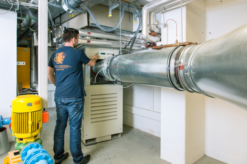
| Laboratory equipment | Micro-gas turbines are small high-speed gas turbines with electrical output of up to about 250 kW. The main components of a micro-gas turbine are a compressor, a recuperator, the combustion chamber, the
turbine and a generator. If the micro-gas turbine is used for cogeneration, it is extended by a module for waste heat utilization. With the Capstone C30, ambient air is drawn in through a centrifugal compressor and compressed to approximately 3.8 bars overpressure. Before entering the combustion chamber, this air is pre-warmed in the recuperator by the hot turbine exhaust gas, which results in a significant improvement of the electrical efficiency. The compressed and pre-warmed air is burned with the fuel natural gas in the combustion chamber. The fuel gas, which is at a temperature of about 800 °C, is expanded in the turbine and drives the compressor and the generator. Before the exhaust gas is fed into a downstream heat exchanger, it cools down to a temperature of about 270°C in the recuperator by pre-warming the compressed combustion air. The Capstone C30 is a so-called single-shaft machine in which power is generated by a permanent generator which is arranged directly on the drive shaft with the turbine and the compressor. At a rated speed of 96,000 rpm, the rated electrical output is 30 kW, and the thermal output with direct utilization of exhaust gas is 70 kW. With cogeneration, the Capstone C30 achieves overall efficiency of up to 78%. |
Pelton turbine
| Laboratory area | Pelton turbine |
| Abbreviated name | Laboratory for Flow Engineering |
| Academic leadership | Prof. Dr.-Ing. Alexandra Jördening |
| Room | D 1.06 |
| Laboratory belongs to | - |
| Workstations | - |
| History | Like the Kaplan turbine, the Pelton turbine is used for environmentally friendly energy generation in hydropower plants; however, unlike the Kaplan turbine, it is not used in river power plants with low drop heights, but only in high-altitude systems with drop heights of up to 2000 m. |
| Tasks and objectives | Using the model turbine in the Laboratory for Flow Engineering, students supplement their existing basic knowledge through suitable experiments. An observation window allows the course of the water jet in the Pelton turbine basin to be followed to improve understanding of the energy transfer mechanism. |
| Laboratory equipment |
|
Flow losses in pipe components
| Laboratory area | Flow losses in pipe components | ||||||||||||||||||||||||||||||||||||||||
| Abbreviated name | Laboratory for Flow Engineering | ||||||||||||||||||||||||||||||||||||||||
| Academic leadership | Prof. Dr.-Ing. Alexandra Jördening | ||||||||||||||||||||||||||||||||||||||||
| Room | D 1.06 | ||||||||||||||||||||||||||||||||||||||||
| Laboratory belongs to | - | ||||||||||||||||||||||||||||||||||||||||
| Workstations | - | ||||||||||||||||||||||||||||||||||||||||
| History | - | ||||||||||||||||||||||||||||||||||||||||
| Tasks and objectives | Knowledge of flow losses in pipe components is important basic know-how for mechanical engineering. The “Flow Mechanics” lecture conveys the theoretical basics needed. Experience has shown that better understanding of the interrelationships can only be achieved through experiments testing what has been learned. | ||||||||||||||||||||||||||||||||||||||||
| Laboratory equipment | The flow losses of important components such as
can be determined in experiments at the above-mentioned test bench by means of pressure distribution measurements in the inflow and outflow of the elements concerned and evaluated in the form of loss figures. The loss figures can be checked for a possible Reynolds number dependence by means of variable flow speeds. |
Wind tunnel

| Laboratory area | Wind tunnel |
| Abbreviated name | Laboratory for Flow Engineering |
| Academic leadership | Prof. Dr.-Ing. Alexandra Jördening |
| Room | D-WK |
| Laboratory belongs to | - |
| Workstations | - |
| History | - |
| Tasks and objectives | - |
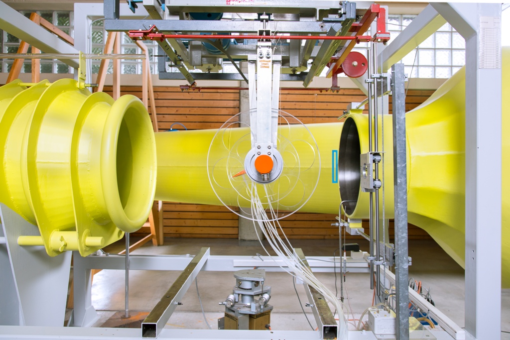
| Laboratory equipment | The department’s wind tunnel is constructed according to the Göttingen standard type for low speeds up to 58 m/s. The Göttingen standard type is a stationary circulating wind tunnel in which the flow medium of air is circulated in a closed circuit using a fan. The air is recirculated from the open measuring section of the tunnel through the diffuser, bladed deflection corners, the rectifier and the nozzle to the antechamber of the measuring section. The fan is far away from the measuring section, as this is the only way disturbances due to swirl and non-uniformity in the downstream installation elements can be compensated for. Ambient pressure and an approximately constant ambient temperature prevail in the measuring section. In terms of measuring technology, the wind tunnel is equipped with modern pressure and force measuring technology. This makes it possible to determine the pressure distributions and force effects on the test specimens clamped in the measuring section. |
Contact | |
Phone: | +49 821 5586-3215 |
