Bell 429 by ROBAN/Scaleflying.de
Review:
How it came about
This page is about my sample of the ROBAN Bell 429 and how I fared with it. That may be helpful for some people, just as it's always helpful for me to read other people's reviews. Some general information about this model is given as well, but most of it can be found in the Web (see "More").
In 2020, I had accumulated six quality flying hours with my HIROBO Schweizer 300. When we had the next Covid-19 lockdown in the following winter, I wanted to own an even bigger model helicopter – probably just craving. The heli should have at least four main rotor blades and again be "scale", so not for aerobatics – sort of appropriate to my age (now even more important).
A model of the Hughes 500 still would have been to my liking, but its body is even bigger than that of the Schweizer 300. That would not only look massive; together with the especially high landing gear it would be "tall" and would hardly go in my car.
So it had to be something more "slim" – like the Bell 429. I knew the Air Zermatt helicopters from TV and YouTube and liked them a lot. A clubmate who owns the 700-size Tiger model by ROBAN/Scaleflying.de hinted at the model. He strongly recommended the 700-size B 429 (and would have recommended an 800-size model if there would be one).
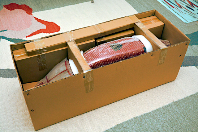
When the package lay on my carpet I had yet a scare about what I had dared to do. But once the helicopter is ready-built I will have become used to its size. Moreover, it will look not that massive out at the flying field, as I know from the 700-size Tiger and an 800-size Airwolf – and bigger flies better, no doubt about that.
The model's size is specified as 700 but the new main rotor blades are 720 mm long – makes 1.60 m main rotor diameter (1.56 m by the instructions). The mechanical assembly is specified as 800-size because it is made for this size. A 700-size motor (of course with a 12s LiPo battery) just fits by diameter and is said to be powerful enough, as well as the recommended 1100 rpm main rotor speed is fast enough. Weight is specified as 8 or 9 kg, depending on where you look for specifications. If the dimensions in the instructions are correct, the model is scaled 1:7 – slightly smaller than the HIROBO Schweizer 300 (1:6.32).
At YouTube I found more than 40 videos of the ROBAN Bell 429 (see "More"). There, mostly a bigger motor (750 or even 800) with higher kv is used (if mentioned at all) and higher main rotor speed. To me that seemed excessive and I rather trusted the recommendations by Scaleflying.de, which have been even confirmed in a reply to my e-mail inquiry (thanks!). Just to turn trust into certainty, the model's drive (see below) and rotors have been rendered in a flight simulator – and yes, the recommendations are correct.
I was a bit worried about my lack of experience. I know how things work but have no hands-on experience. The HIROBO Schweizer 300 was good practice for me, but its whole build was perfectly prepared and described. Before buying the B 429 model, I had downloaded the instructions from the Scaleflying.de website. They seemed to be rather short and a bit confusing, and that proved to be true when the kit had been delivered. Three additional sheets added important information not yet included in the instructions (version 2.0 – May 2016) and that was it.
Scaleflying.de has four useful videos at their YouTube channel which show important aspects of their 800-size mechanical assembly. They point out that its main part is pre-assembled but has to be dismantled just to re-assemble the whole thing using threadlocker. Besides, the bevel gear's backlash has to be checked and, if needed, adjusted with shims included in the kit, as well as – in this new version – the bearing clearance of the angular ball bearing on the main rotor shaft.
I was annoyed when I heared that I should use heat to unloose bolts if they are stuck by threadlocker. My clubmate thinks that pre-assembling saves packaging the many parts and describing their assembly. That makes sense to me, but why did they use threadlocker then and – as it turned out later – shims to adjust the bevel gear as well as the angular ball bearing, and why did they grease them? To me it rather looks like an exclusion of liability and that hampered me at first.
Assembly
The helicopter is sold for a really reasonable price but still it costs a lot of money. That's why I declared it a Christmas gift and didn't unpack it until Christmas Day. The remaining time was used to purchase the necessary (and not cheap either) components: servos, gyro (flybarless) system, receiver, telemetry, motor, ESC, main switch, dual receiver-battery switch – but no batteries yet. At Christmas Day, the kit was unboxed and – first of all – the mechanical parts were inspected.
Mechanical Assembly
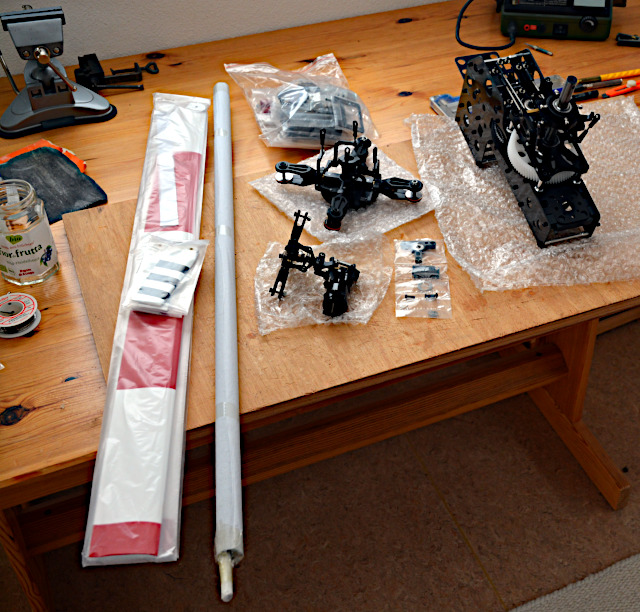
From right to left: mechanical assembly, wrapped parts of the motor shaft support bearing, main rotor head, tail rotor assembly with bevel gear, tail boom with tail rotor shaft (wrapped), main and tail rotor blades – wonderful!
I was especially glad to have the latest, improved version: motor shaft support bearing, helically toothed main gear, angular ball bearing on the main rotor shaft, longer servo-swashplate levers, hence longer servo arms, longer rotor blades, reflexed main rotor blade airfoil.
But should I really dismantle that? Enjoyment gave way to annoyance. All too often I didn't want to concern myself with the helicopter. At times when I was more sober I watched the instructional videos by Scaleflying.de, read about gear assembly, and inspected the mechanical assembly and the rotor heads again and again.
Eventually, there are nine months between this picture and the next one. In the summer, things started to happen really fast. The rotor heads were checked and turned out to be securely bolted (with threadlocker). The mechanical assembly was partially dismantled in order to reverse the bevel gear, then reassembled with threadlocker.
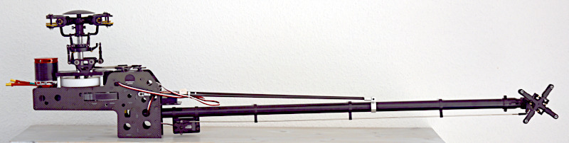
The result is really to my liking, even if I'm still not confident – about the screwlock, the bevel gear backlash, the bearing clearance. By the way, the tail boom is really a bit inclined upwards; that's how it runs in the tail cone. The ROBAN 800 mechanical assembly is basically the same in all of their models, but the carbon frame sides are different. In the B 429 model, the tail boom is just inclined and quite high in the body. And there is no 45° bevel gear in the tail boom like in the Tiger model.
The two carbon tail-boom struts are bolted and clamped with aluminum fittings. In one of the videos by Scaleflying.de they mention that these struts are affixed differently, depending on the mechanical-assembly frame in the respective model. They have to be bolted to the carbon frame sides where washers are under the bolt heads. That's how it was and now the whole assembly goes through the rear opening in the body, so all seems to be correct.
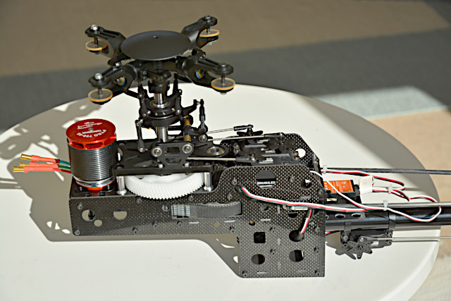
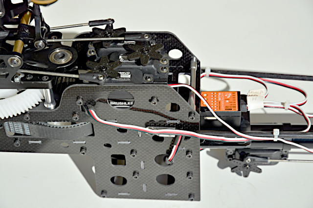
The motor moves a cogged belt which is visible outside the carbon frame side. Above the big pulley is a pinion which moves the big white plastic cogwheel visible here and thereby the main rotor shaft.
The three 120°-swashplate servos are linked by one 90° bell crank each. In this latest version of the mechanical assembly, the bell cranks are bigger so the servo arms are longer than before, and all three pushrods have the same length now.
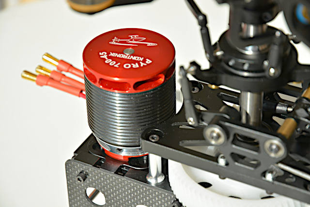
The KONTRONIK Pyro 700-45 (kv 450) has been chosen due to the positive experience with the Pyro 600-09 (kv 930) in my HIROBO Schweizer 300. It has about half as big a kv and a 12s LiPo is used instead of a 6s.
A more powerful motor is not needed according to Scaleflying.de. If I would like to use one, though, its diameter should be not much bigger so it would still fit in the frame's recess.
The motor sits on a carriage which is pulled forward (left in the picture) by two bolts to tension the cogged belt.
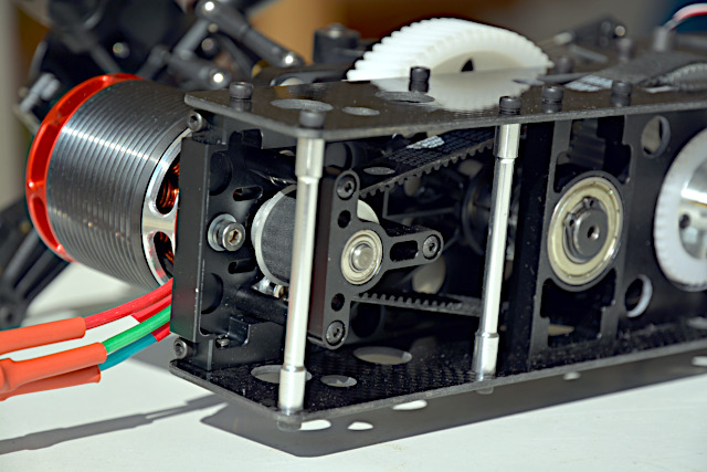
The two tensioning bolts are visible here as well as the whole cogged belt gear train. When the belt is tensioned correctly, the four bolts clamping the motor are tightened. I used shiny bolts and washers (well visible here) while (quite short) black ones were included in the kit.
The T-shaped part is the motor shaft support bearing. It has three "legs" which are clamped – together with motor and carriage – by three of the four clamping bolts. That's quite a fiddling but doable. I just hope that I didn't cause any tension on the motor shaft when tightening the bolts.
If I didn't, the support bearing prevents permanent cantilever load on the motor shaft so it's a very good thing. A precondition is choosing the motor version with the longest shaft available – 38,5 mm. And the cogged-belt pinion has to be mounted with its set screws towards the motor – not like shown in the standard instructions but like shown in the special instructions for the support bearing and in the video.
By the way, I had hoped that the cogged belt would run centered between the pinion's lateral disks. However, the test run showed that it follows gravity and runs against the lower disk. I had to loosen the pinion again and shift it one millimeter upwards (towards the motor) so during operation the cogged belt runs centered on the big pulley.
The cogged-belt gear train's numbers of theeth are 22 and 78 – 3.55:1 reduction ratio. The following gear train with helically toothed steel pinion and plastic cogwheel has 20 and 78 teeth, respectively – 3.9:1 reduction ratio. Hence the total reduction ratio is 13.83:1 from motor to main rotor. Assuming the recommended 1100 rpm main rotor speed, the motor has to spin at 15210 rpm – no problem considering 30000 rpm maximum rotational speed (and 12s LiPo).
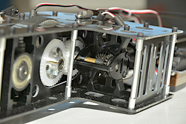
Below the big cogged pulley is the first (white plastic) gear of the tail rotor gear train. The second behind it moves the vertical shaft of the bevel gear below it. The latter's gear ratio – as well as the bevel gear's on the tail rotor – is 1:1.
The two plastic gears' numbers of teeth are 40 and 32, what makes for a 1:1.25 transmission ratio. Together with the cogged-belt gear train's 3.55:1 reduction ratio, the total reduction ratio is 2.84:1 from motor to tail rotor. At 1100 rpm main rotor speed, the tail rotor spins at 5363 rpm. With its 290 mm diameter (280 mm by the instructions) and its four blades it should have quite some power (and the simulator confirmed that).
The bevel gear has been "reversed", that is the bevel wheel on the vertical shaft has been relocated from top to bottom, to reverse the tail rotor's sense of rotation. Now it turns the right way round, like on the original helicopter and like it should be "aerodynamically".
This bevel gear still worries me even though all looks good and works correctly. An instruction sheet was included in the kit, which points out that the bevel gear has to be adjusted, and there the bevel gear is shown like here. Probably the picture shows another helicopter model's bevel gear, though. Anyway, the shaft's flat portion for the wheel's set screw was not symmetrical and had to be extended (with a grinding wheel on a Dremel). So the tail rotor's wrong sense of rotation must have been intended by the designer. I asked Scaleflying.de by e-mail whether there is a special reason for that or any reason to not reverse the gear, but they just didn't reply.
Reversing the bevel gear was an opportunity to inspect all details. To this end, I removed the whole gear from the carbon frame, what was quite elaborate. I could have done it easier by removing the lower bearing plate and unloosing the wheel set screws. The shaft could be pulled out then as well as both wheels and the brass spacer sleeve. Originally, the bevel wheel was on top (left in the picture) and the spacer sleeve below. Now it's just the other way round and all works well like before.
Above the bevel wheel were two shims to adjust the backlash. Of course, the shims were put under the wheel when it was reversed. As far as I can see, the gear was adjusted correctly then. I just can't rely on that because Scaleflying.de would not be liable for any damage. That's not a theoretical problem – my clubmate lost his Tiger model twice in crashes because the 45° bevel gear in the tail boom failed. Of course it was his fault, meaning he got no compensation. (Now he installs a flexible shaft instead.)
For three reasons I believe (or hope) that my B 429 won't crash due to gear failure: (1) The 90° bevel gears seem to be not so prone to fail or in any way critical, perhaps because they are easier to adjust or factory adjusted – who knows. (2) When inspecting the bevel gear I realized that both bevel wheels have to be adjusted so that their teeth are not offset to each other. (The teeth of the failed 45° bevel gears are stripped, but on one of the wheels only partially, that is not their outer part.) If that's not correctly done, also the backlash can't be correctly adjusted at all. (3) The 90° bevel gears have rigid open chassis so correct adjustment is visible. The 45° bevel gears have somewhat sloppy split closed housings so that the final adjustment is not visible and perhaps a correct adjustment is not even really likely.
ROBAN should really do like HIROBO: By all means, such a gear like the 45° bevel gear has to be prefabricated – assembled and adjusted. Perhaps they could design it in a way that no adjustment is needed, or at least they could use a fixture to easily and reliably adjust the gears – in the factory. They ought to accept responsibility, that is assume liability, but they won't possibly get that right.
However, I still don't know how to adjust the gears correctly and can guess only. Mr. Illig from Scaleflying.de shows in his video how to tension the cogged belt. But he just pokes around in the bevel gear with a screwdriver (there is no help for it, there's nothing to be seen) and tells that the bevel gear has to be adjusted – but not how. As far as I can see, the bevel gear was adjusted correctly, that is I couldn't do it any better.
That applied to the bevel gear on the tail rotor as well. It's made from the same parts as the front bevel gear; the bearing plates are just closer to each other. It's easy to check that the two bevel wheels are correctly positioned to each other. And the correct backlash can be checked by turning the shaft to and fro. The wheels were greased already.
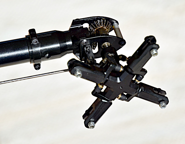
The tail rotor has been converted to the reversed sense of rotation: the pitch lever links removed from the link balls, the blade holders reversed so the pitch levers "lead", the link balls unscrewed and screwed in from the other side (with threadlock of course), the pitch lever links snapped on again.
Now the tail rotor turns clockwise (as seen like here in the picture), the tail rotor blades moving backwards at the top, with the main rotor's wake and not against it. That's how it is on the original helicopter and that's (almost always) aerodynamically correct.
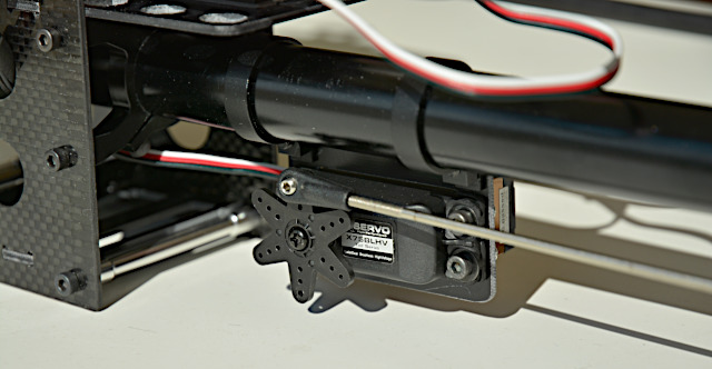
The tail servo (XServo X75 BLHV) is clamped to the tail boom – a simple and neat solution. In the instructions and in pictures I saw at least four different ways to mount the clamps, the plate and the servo and how straight or oblique the whole thing is clamped to the boom. This was one of these ways and it seemed to me the way actually meant by the designer.
The tail boom is made from very thin aluminum and its front end was a bit crimped in, probably during transport. With some force, it had to be stuck and turned into the receptacle on the front bevel gear. Fortunately, I didn't crush anything in the process.
Also the swashplate servos (XServo X70 BLHV) are well linked. They are mounted in a special frame so that all three pushrods to the bellcranks have the same length.
The ball links are made from a quite hard plastic and (hence?) have a little bit of slackness. That's strange – so far I had only links made from ductile plastic and had to press them with flat pliers so they are not too tight.
There's an own place for the gyro system (Microbeast Plus HD) so it's close to the servos and exactly parallel to the main rotor disk. The servo leads are protected from rubbing on the sharp edges of the carbon frame by wrapping them in slashed pieces of fuel tube.
There was some bother about the servo arms: The instructions recommend metal (aluminum) arms. An additional instruction sheet specifies at least 13 mm lever arm for the new-version swashplate linkage. Aluminum servo arms are hard to get in any case, especially 13 mm lever arm, and I found only one offered in the Web. Unfortunately, it doesn't fit the servo shaft (not properly deburred, swollen when anodized, but also servo shaft too big!) and has a 3 mm threaded hole instead of 2 mm. In a video by Scaleflying.de, Mr. Illig says that metal servo arms are hard to get but using plastic arms is OK. So now the supplied plastic arms are on the servos – with 13 mm lever arm.
The mechanical assembly is an operative unit. Earlier versions even had a "porch" for the ESC with two more mounting lugs, but obviously that has been abandoned. Now four lugs must do and the ESC is screwed to the top of the cabin ceiling in front of the mechanical assembly.
After it's completion, the mechanical assembly has been test-run with the 12s drive batteries. The ESC was set up as a governor and the set rotor speed has been defined. After a short break-in of gears and bearings all ran smoothly and with low friction. Amperage – as indicated by the ESC's telemetry – is a measure of friction moment and suggests about 94% overall (main and tail rotor) gear efficiency.
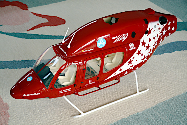
Body
The struts of the landing gear halves are stuck through holes in the fiberglass body into a plywood structure inside, then fastend by stick-through bolts. Actually, that's a good solution but the right rear strut went not deep enough into the hole so finally some pieces of epoxi chipped off – fortunately only below the strut where it's not visible.
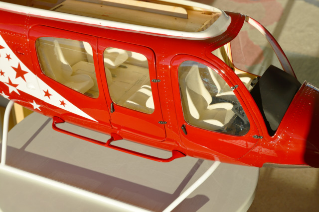
Just because they are well visible here: door hinges and handles are not really prototypical but not too bad either. They are a bit coarse but stand out just as little as the badly glued-on footsteps.
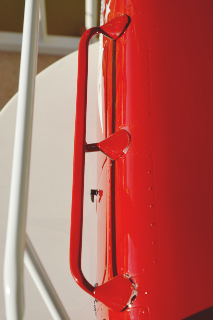
My problem is visible here: The footstep's midlle attachment is glued-on flush but the other two at the front and the back stick out a bit. The footstep is so rigid that rubber bands, adhesive tape, and later the glue slackened. Now some Canopy Glue will somewhat fill the gaps.
This is a bottom view of the gaps; later they will stand out very little, see previous picture.
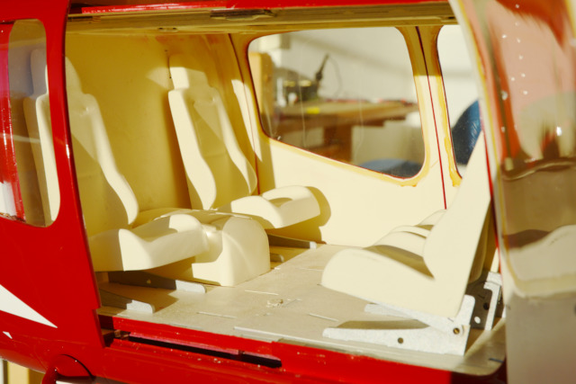
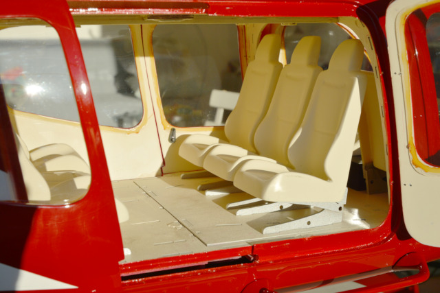
The doors are flush-mounted and look pretty good. The interior equipment, mostly seats, has to be glued to the beige-colored plywood cabin floor – that's all. Looks pretty good as well.
There are tabs on the bottom of the seat pedestals, which are stuck into slots in the floor (hardly visible in the picture). So it's perfectly clear where the seats go in the cabin; they can be glued on only there.
The box in the middle has a fuction: It's a handle on a slider which locks and unlocks the hatch in the cabin floor in front of it. The box is grabbed to move the slider back and forth.
Three seats are on the cabin floor hatch, and they are used as a handle to remove the hatch and get at the battery compartment.
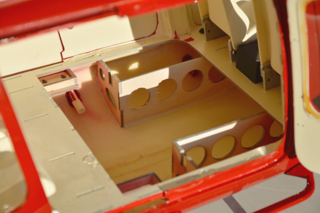
In the middle is room for two 6s 5000mAh LiPo batteries and on the sides for two receiver batteries. Behind them (left in the picture) is room for other things to be placed here (master switch for the drive batteries, dual switch mixer for the receiver batteries, telemetry sensors) as well as cables and connectors.
The cables to the ESC on top of the cabin ceiling can be threaded through the vertical plywood duct visible in the background (behind the corner of the hatch opening). In front of the battery compartment (right in the picture) are the pilots' seats, which are seen from above in the next picture.
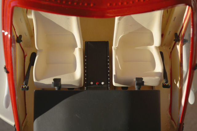
This picture is about sticks, though, that is the cyclic and collective control sticks.
In the full-size helicopter, the pilot is in the right seat (left in the picture) and his collective stick is on his left, not on his right like here in the model helicopter. The model's seat would have to be more to the right side and the collective stick between seat and the center console (but it's not really easy to glue them that way due to the tabs and slots). There is even another, smaller console on the center console's right side (below the panel, not visible here) so a pilot manikin's left leg would have not enough room.
Seems the model's designer missed something, but then again he went to great effort: The switch box on top of a cyclic stick is asymmetric and here both sticks are inversely asymmetric because the pilot uses his left hand and the copilot his right hand in this arrangement. Actually, both cyclic sticks should be equal because both pilots have them in their right hands (and the collective sticks in their left).

The tail has to be bolted to the body with six 2mm bolts, a foam piece on the tail boom carrying the tail's weight. At least I don't think the small bolts are capable to do that on that long lever arm. The holes can or have to be drilled – with tentatively fixated tail – without support. The drive-in nuts on square plywood pieces were included in the kit. Because they are hardly accessible later they have been glued in already.
The front window has been screwed on.
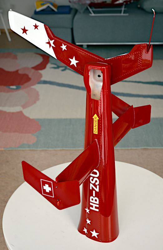
The decals have been applied – following the instructional video by Scaleflying.de. My UAS operator ID (e-ID) as a QR code is hidden between the stars in front of the black exhaust nozzle.
The two dummy antennas on the top cowling are glued on. Glueing another five dummy antennas is saved until last so they are not broken off while I'm further working on the helicopter.
Especially without direct sunlight the model's red color seems too dark to me – compared to the original as well as to other models. Perhaps they used a paint that looks different in different lighting, but I think this shade of red doesn't quite match the original (but it does match the carpet).
Tail
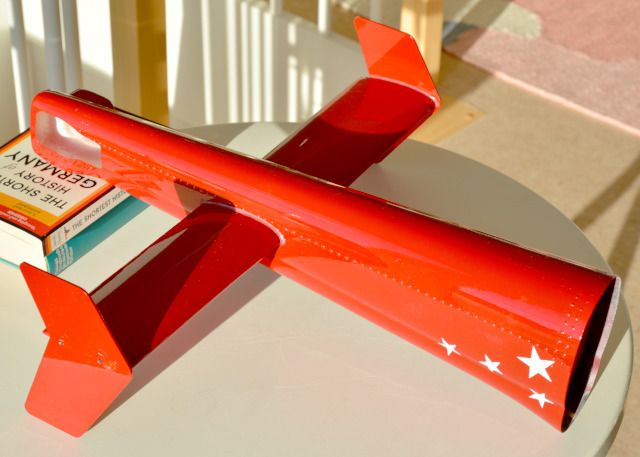
On to the tail: In the tail cone runs the actual tail boom with the tail rotor shaft. That's why the horizontal stabilizer can't be sticked through in one piece, and two halves have to be glued into recesses in the cone instead.
At the stab tips are fins (screwed but glued as well) with very nice, small position lights (glued on). I was scatty again and fastened them the wrong way up, their longer side upwards, but that's not a problem and just one more non-prototypical trifle.

By the way, the tail is here upside down because the stab halves were aligned while the glue was setting. It's Canopy glue again because it bonds so well on smooth plastic surfaces and because it stays a bit elastic. And when it's cured it hardly stands out.
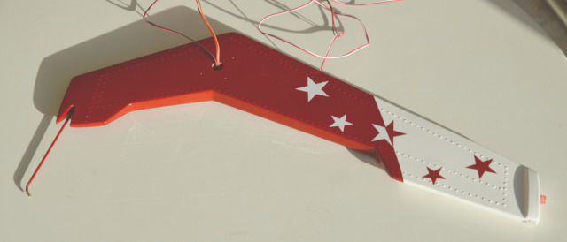
This big fin with tail skid and two lights has to be screwed to the tailcone's rear. Four indentations for screw holes are visible around the cable exit. The cables belong to the lights which are glued to the fin's top. The skid is simply screwed into a wooden filler.
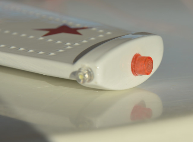
The nice red anti-collision light was included in the kit, but no white rear position light – another mysterious deviation from "scale". I took one LED from a Multiplex light set and glued it on where the original's rear position light is. Drilling a hole for the cable was no problem since the whole fin is hollow plastic.
The big central fin is screwed on – one black screw head is visible in the opening. In the tail cone as well as in the fin were four indentations each for screw holes. In the tail cone, the fiberglass plastic has to be drilled out for the 3mm screws. In the fin – plastic with wooden filler – 1mm or 1.5mm holes suffice to let the screws go in without breaking. (All screws and bolts included in the kit seem to be brittle and are sheared off easily.)
The holes in tail cone and fin matched, so the fin was screwed on. Now it seemed to be badly bent forward, and compared to the original helicopter it was. So it was taken off again and three of the holes in the tail cone were made slotted holes (more forward and/or upward) using the drill bit's stem (side) like a milling cutter. (The upward slotted hole is visible in the picture.) When the fin was again screwed on it was perfectly upright. Seems to be a flaw in the molds.
The fins attached to the stab the wrong way up are visible in this picture. Now their upper and lower parts' sweep doesn't match the central fin's but that is virtually invisible. The main rotor is high enough to avoid any fin strike. (And at Scaleflying.de I saw a picture of another B 429 model with the side fins just as wrongly attached as here.)
All four lights are plugged and tested – looking good. The light controller included in the kit is not too bad. (Newer kits include a different controller.) It has three free connectors for rear position lights of which one is used here. It can be switched (with a transmitter switch) to different blinking patterns of which one is prototypical. (I had to find out by trial and error, no instructions.) Only the red anti-collision light is blinking then, in fact so smoothly that I don't want a different controller. Because it works only at voltages up to 6V I even had to slot a voltage regulator in ahead, but that was worth it for me.
The decals are applied (well visible) and the six holes for the fastening bolts close to the forward edge are drilled (hardly visible).
Electronics
Pending…
Completion
All rotor blades have been balanced beforehand. Since main and tail rotor have four blades each, the two lightest and the two heaviest of each rotor have been identified (with the blade balance). The pairs have been labeled with colored adhesive tape (red-green and yellow-blue) and balanced with the white adhesive tape included in the kit under the respective lighter blade's tip. Quite a few people claim that ROBAN blades vary a lot in weight, but not much tape was needed here – perhaps because balance can be done in pairs. The blade holders have been labeled with correspondingly colored adhesive tape so that the blades are facing one another by pairs. That way each blade will always go to the same holder and any individual blade angle adjustment persists. (The linkages from the blade holders to the swashplate stay bolted to the blade holders so no color tags are needed on them.)
The rest is pending…
Flying
Pending…
The Bottom Line
… just as a few notes:
- Nice, prototypical model.
- Minor details are not scale.
- Substantially built, good quality, attractive price.
- Well-designed mechanical assembly.
- The tail rotor's sense of rotation can be reversed to CW.
- The tail rotor does spin during autorotation.
- Not for rookies – experience helps.
- But not really challenging, either.
For – even some challenging – details see previous sections.
More
Wikipedia article about the Bell 429
Air Zermatt Bell 429 pictures at airliners.net
Web page by Bell about their 429
ROBAN MODEL (in China) web pages (English)
Scaleflying.de web pages (English)
Web page by Scaleflying.de about the ROBAN Bell 429 Air Zermatt (English)
Web page by Scaleflying.de about the ROBAN Bell 429 Air Zermatt in the Web Archive
YouTube channel of Scaleflying.de (German)
Web page by KONTRONIK about the Pyro 700-45 motor (English)
Web page by YGE about their high-voltage ESCs, especially Opto 135 (English)
ROBAN Bell 429 build thread at rc-heli.de (German)
another ROBAN Bell 429 build thread at rc-heli.de (German)
ROBAN Bell 429 build thread at vstabi.info (Mikado forum, German)
ROBAN AS350 review by John Salt (English)
Telemetry
This model helicopter, like my HIROBO Schweizer 300, has a modern electric drive with a governor. Hence it just has to be equipped with modern telemetry as well to ensure flight safety.
Receiver and ESC provide even half of the displayed values; just two extra sensors are used to monitor the voltages of both drive batteries. For later interpretation of these data, a GPS adds 3D location data. The FlightRecorder logs all telemetry data so they can be analyzed later – routinely or possibly after an accident.
Most of the values are not just logged and transmitted but also monitored for exceeding or falling below adjustable limits. Values and any "alarms" are shown on the transmitter display and announced by voice-output. That needs a sensible setup and therefore I devise a coherent plan in the form of a spreadsheet.
Sensor Setup
My new transmitter has an operating system similar to that of a smartphone and a touch screen. In the telemetry display pages, the font size and hence the number of displayed values is adjustable. For me, six rows (values) per page is the best compromise between overview and readability. The display has been adjusted to that by dragging the touch pen. In this plan, two pages with six rows each are marked off by red lines so a third page with four rows remains:
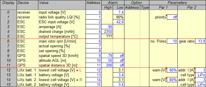
These are the basic telemetry device settings. Up to 16 values may be transmitted on the MSB; the display sequence (leftmost column) follows from the chosen bus addresses (fourth column).
Alarm means optional upper and lower alarm thresholds while Parameters are mandatory and have to be set in the respective devices. (Options – that is maximum, minimum, or mean values – are not needed here because all telemetry data are logged.)
All of the possible 16 values are used here but no special allocation to pages has been tried. The values of the five devices on the sensor bus have been just put in consecutive rows. Yet the resulting partitioning is quite useful: The first page with values interesting during flight is followed by a second page with values meant for later analysis and a third (shorter) page with all drive battery voltages.
The two values delivered by the receiver have been left in their default places 0 and 1 so the transmitter's warning LED for too low receiver voltage will work. For a 2s LiPo receiver battery, 7.4 V under load is a safe warning (or alarm) threshold because it implies there is enough charge left for landing. "Priority off" means none of the values (or addresses) is transmitted more frequently than the others – that would be actually needed just for a high-resolution variometer tone.
The ESC provides seven values – all of them interesting. The controller's "actual opening" and "set opening" are new to me and especially interesting. The order of values has been changed only in that "drained charge" has been put in place 4 so the transmitter's warning LED for too low battery charge will work. In exchange, the "main rotor rpm" has been put in place 6. Number of motor poles and gear ratio have to be specified because rotor rpm is derived from the motor's field frequency by calculation.
"ESC input voltage" is actually redundant since it will be only slightly lower than the voltage measured directly by the voltage sensors on the batteries (due to the resistances in between). Still the low-voltage warning is activated as an alternative solution. The trigger level is set to 42.0 V total battery voltage, corresponding to and as replacement for 3.5 V per cell – the level actually wanted but not possible with the voltage sensors.
For "amperage", the high-amperage warning trigger level is set to 90 A – far more than the expected 40 A peak, far less than the ESC's 135 A rating and the (40C) batteries' 200 A rating, but about what the motor can stand for a short while.
Both batteries – 6s 5000mAh 40/80C LiPo each – are charged to only 4.18 V (instead of 4.20 V) per cell, which is why capacity is only 4850 mAh (97% of nominal capacity). 20% is deducted to anticipate degradation by usage and age, so 3850 mAh are left. At 30% remaining charge, that is 1500 mAh, a low-charge warning should be issued. The ESC simply counts "drained charge" so the warning trigger level has to be set to 2350 mAh.
The GPS 3D location data are logged by the FlightRecorder in any case. They are used to render a flight path in Google Earth. In diagrams, "spatial speed 3D" and "altitude AGL" as well as perhaps also "spatial distance 3D" are useful data to be plotted over time. These have to be displayed (sent on the MSB) during flight so that the FlightRecorder can log them. The three upper warning levels have been activated. The GPS is set to "slow aircraft", meaning horizontal speeds up to 79 km/h and vertical speeds up to 54 km/h. The "spatial speed 3D" warning trigger level is simply set to 79 km/h. An "altitude AGL" warning is triggered at 50 m, our least limit when the control zone is active and my limit to keep orientation. For the same reason, my personal limit of 200 m is set as "spatial distance 3D" warning level.
Immediately after the special voltage sensors have been plugged to their respective drive battery, they check their cell voltages and report their state of charge (in %) in the place of cell voltage. If one of the cells is below the voltage characteristic for "LiPo" cells charged "80%", a warning is issued – a safety feature. Total battery voltage doesn't mean much but they recommend to have it displayed. Then, if the 3.4 V cell voltage threshold (set here) is underrun, the respective warning is displayed in the place of total voltage. Only the so-called absolute low-voltage alarm (threshold 3.1 V preset for LiPo) is shown in the place of cell voltage. The 3.4 V warning threshold is the default value and is tried and trusted by me – it's not too high. It should be even raised to 3.5 V for an earlier warning (at 25% remaining charge instead of 15%), but the sensors don't allow that. Still they are good for another warning stage, detecting a too low single cell voltage. If the sensors know the amperage value's address ("3"), they can refrain from issuing low-voltage warnings in case of short amperage peaks.
Safety Plan
The warning trigger levels have been chosen so that the helicopter is as safe as possible and the batteries are taken care of:
In normal circumstances, the ESC's low-charge warning comes first at 30% (nominally) remaining charge. Then, at about 25% (really) remaining charge, the 42.0 V battery voltage level – equivalent to 3.5 V per cell – is underrun. If not after the first warning already, the helicopter should be landed after this second warning.
For once the voltage sensors warn at 3.4 V cell voltage, remaining charge is only about 15%. That is already detrimental to the batteries but still enough for a safe landing before the ESC reduces power so much that cell voltage is kept up at 3.3 V in order to avoid an immediate battery damage.
So the low-charge warning is the actual advice to land soon – like a white reminder light in a cockpit. 42.0 V battery voltage (equivalent to 3.5 V cell voltage) is an urgent request to land very soon (ASAP) – like a yellow warning light. 3.4 V cell voltage is the last warning to land immediately – like a red alarm light. After that, you would at least partially lose control because eventually power is reduced too much for flying.
Circumstances are not normal if the batteries are cold or old. In these cases, they have not (any longer) their nominal capacity and the low-voltage warnings are triggered soon after the low-charge warning, in extreme cases even before. We can rely on that because a helicopter – unlike an airplane – permanently draws a lot of amperage.
In case of a bad cell, the voltage sensors can warn just in time, possibly without any other warning issued before. So you must always pay attention to a warning's type – the red light may light up unexpectedly.
(This safety plan's rationale is explained here.)
Voice Output
My new Cockpit SX 12 transmitter (bought in 2020) has built-in voice output, which is configurable but simpler compared to the Souffleur used with the old ROYALpro9 transmitter (bought in 2008). With a bit effort, it's possible to generate special sensor value announcements and load them into the transmitter. However, these announcements are bound to fixed addresses then. So for all models the same respective addresses (for instance for rotor speed) would have to be used. That's virtually impossible so the standard announcements (for instance “sensor 3”) are even more meaningful. They are useless, though, which is why I replaced all of them by a short beep to shorten announcement time. It's still possible to distinguish all announcements by their units, or at least by their values, and short announcements are good in any case.
Several values can be included in only one group which is announced at one go. But not only a switch can trigger the annoncement but also tilting or moving the transmitter. That's how I trigger the announcement of a few critical values: amperage, drained charge, ESC temperature, and lowest cell voltages. Separately, remaining flight time is announced by tilting the transmitter.
By the way, voice output is also assigned to switch positions. That's very convenient for me since I keep forgetting which switch and position is assigned to which function. Now I can simply try and I'm prompted. Of course, I do that only before the helicopter is activated; then I can again keep it in mind for the next few flights.
Drive
To render the model's performance in the REFLEX XTR² flight simulator, the drive characteristics had to be ascertained. "Drive" means electric motor, main and tail rotor gears and shafts, and both rotor heads. Some parameters were specified by the motor and model manufacturers, respectively, some had to be measured, and the rest was calculated.
Parameters
The motor's manufacturer specified 450 rpm/V specific rotational speed (kv) and 32 mΩ (milliOhm) internal resistance (impedance, Ri). The third characteristic required to calculate the motor's performance, idle (no-load) amperage (current, I0), had to be measured. To this end, the motor was just clamped to the workbench and run with the designated ESC/governor and a 10s LiPo battery. The ESC's telemetry showed both rotational speed and amperage. I0 turned out to be 2.3 A at 15800 rpm (equivalent to 1143 rpm main rotor speed).
Similarly, amperage was measured after the mechanical assembly had been made ready (see above where also the gear ratios are specified). The ESC/governor was set to 1100 rpm main rotor speed and after some run-in of the whole drive the no-load (no blades) amperage I0 turned out to be 3.3 A now. So main and tail rotor "gear" made for an additional 1.0 A amperage draw. A simple calculation resulted in 94.5% "gear" efficiency (which, as the percentage of torque transmission, by definition includes any additional friction losses under load).
That, the specified gear ratios, and the measured blade lenghts and widths are enough to render the drive in the flight simulator. I didn't even check the specified values (except the gear ratios) because that would be hard and because the calculations are simplifications, anyway.
Maximum Power
In the simulator, the motor's mechanical-power characteristic is approximated. For that, maximum mechanical power has to be specified as well as the rotational speed at which it occurs. Both can be calculated from the specified drive parameters. However, the resistance of batteries, ESC, and leads (including connectors) has to be estimated. From the charger's display, 30 mΩ have been taken as one battery's resistance, and 20 mΩ have been assumed for ESC, leads, and connectors. The calculation spreadsheet is available for download.
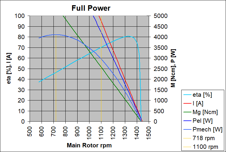
By way of calculation, maximum mechanical power is 4110 W at 718 rpm rotor speed, corresponding to 9930 rpm motor speed. These values are needed for the simulator only.
In practice, the motor can't deliver this power because amperage would be far too high. Even at the designated 1100 rpm set rotor speed, amperage would be 95 A and still too high. However, if the ESC would draw only short bursts of full power at a constant 1100 rpm main rotor speed, that would be harmless for the motor (for the ESC in any case). On average, amperage is not even half as high.