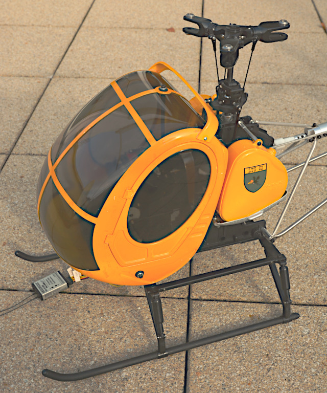
Schweizer 300 by HIROBO
Review:
How it came about
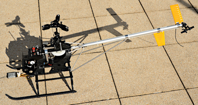
This page is especially about my sample of the HIROBO Schweizer 300 and its specific features. Of course, general information about this model is given as well.
To my own surprise, I finally got the hang of nose-in hovering in 2017. Now I wanted to own a "real" model helicopter, not only micros. It should be even quite big and heavy, have an electric motor, and be "scale", so not for aerobatics – sort of appropriate to my age.
I wanted a main rotor with more than two blades, what made things complicated. A model of the Hughes 500 would have been to my liking, but there were only fiberglass bodies and five-blade rotors by different special manufacturers. Finding suitable ones and fitting them to a standard "pod-and-boom" heli as a basis would have been too difficult for me and quite expensive.
In the Internet, or Web for that matter, I found this model, which is "scale" in the first place and for which a three-blade main rotor is available from its manufacturer HIROBO. Besides, TMRF Rüdiger Feil, expert and distributor for HIROBO in Germany, makes an electric conversion kit. That seemed convenient to me, the more so as a few modelers reported success with this combination in German web forums. And the Hughes or Schweizer 300 has always appealed to me.
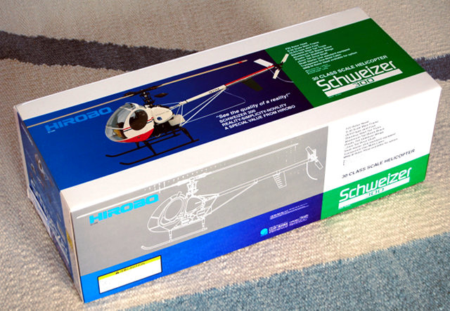
On the kit box is printed "30 class scale helicopter", and that's correct. HIROBO had brought out this model as early as 1995 and obviously didn't modify at least the box art ever since. Back then there were only glow engines, and a .30 (5 ccm) was the standard size for sports and trainer helicopters. HIROBO's advertising claims that more than half of all model heli pilots worldwide have learned to fly with a HIROBO Shuttle. That may be even true, particularly since the model has been sold since 1985. Anyway, probably they derived this S-300 from the old Shuttle and both have several parts in common.
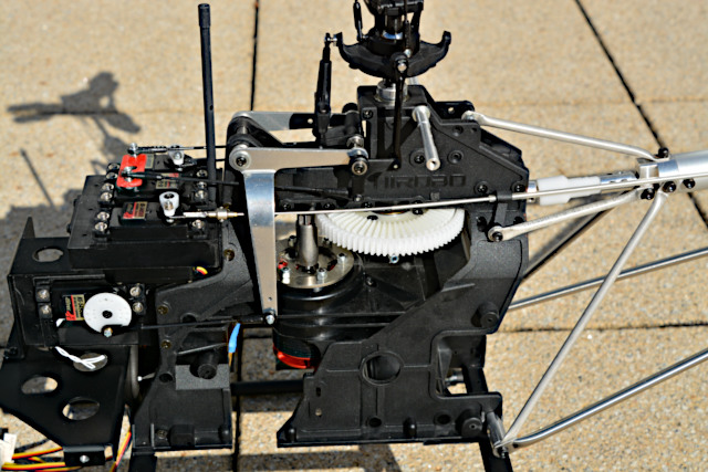
That should also pertain to the main rotor – as usual back then a two-blader with flybar (paddles) and mechanical mixers to the swashplate. On the main frame are mechanical mixers actuating the swashplate by means of three "standard size" servos. The tail rotor is driven by bevel gears and shafts – an advantage for me since I just dislike belt drives.
Nowadays, a 1244 mm diameter rotor (2000 rpm maximum speed), with blades exactly 550 mm long, would characterize a 550 class helicopter with typically 2.8 kg weight. KYOSHO specifies 3.2 kg weight already for the classic-design S-300, but a version with three-blade main rotor and electric motor will be even heavier (rather 4.2 kg). Adequately, .46 (7.5 ccm) glow engines are often preferred or today a powerful electric motor with up to 2 kW power and a 6s LiPo battery.
How long the three-blade rotor has been available is not known to me, but it is a well-made rigid all-metal rotor head with wooden blades – classic like the whole heli. Its diameter is 1092 mm (blades 477 mm long) and it should be operated at speeds between 1500 and 1600 rpm (1800 rpm maximum) so it will need quite some power. As per Rüdiger Feil, who is a well-known competition flier (and "heli guru"), the model flies quite well even "conventionally" (with a gyro for the tail rotor only), but HIROBO recommends a "commercially available 3-axis gyro" (flybarless system) nonetheless. The model is not capable of doing aerobatics, due to the mere fact that the main rotor blades have cambered airfoil and only small negative pitch angles.
That "scale" on the kit box may be not completely true, considering the two-blade main rotor, but otherwise the HIROBO S-300 looks as true to the original as hardly any other S-300 model (especially due to the slanted tail boom). The three-blade rotor is even closer to the original, even if it needs to have a more massive head and wider blades. So all could be fine and dandy if I wouldn't always find fault with something – see next section.
Though the kit box pictured above with its print and box art has been left unchanged since 1995, this box contained all the modern parts I had actually ordered (three-blade main rotor, electric conversion kit) and not any old dispensable parts (for a two-blade main rotor or a glow engine). All were neatly put together and packed by TMRF Rüdiger Feil. Included were instruction manuals for the basic kit version and for the optional three-blade rotor, as well as a few sheets about electric conversion. The instructions (text in Japanese and English) are unusually comprehensive and correct. All required data can be found, even if not exactly easily due to the manuals' sheer size. Electronic versions (PDF) can be downloaded from the HIROBO website, but they are not searchable (seemingly not made with a text program).
The instructions should, or better must be carefully perused and collated, and there are several things in the three-blade rotor manual overriding directives in the basic manual. Of course, there are no suggestions for modifications, but with some effort it's well possible to discern how to modify something. I wanted to reverse the main rotor's sense of rotation since, as supplied, it's "the wrong way round". With active support by Rüdiger Feil, the necessary modifications basically worked out, albeit without warranty to work properly. The risk was worth it to me, though, the more so as the modifications can be undone (even if with some effort).
My Modifications
Only a build thread in a German web forum drew my attention to the "problem": the horizontal stabilizer, which is slanted up by 30°, is blown by the tail rotor. In hover flight, that makes for turbulence and prevents the helicopter from standing still in the air. As a remedy, someone suggested and tried to install the horizontal stab really horizontally, or level, and that helped it. That goes against the grain for me, though, so I perused the instructions in search of the reason why a problem like that can occur on a scale heli. Soon enough this reason was clear, just trying to provide a remedy became quite a project then.
The HIROBO Shuttle's configuration, with a glow engine turning clockwise down in the main frame, makes for a main rotor turning clockwise (seen from above) as well. Like on any full-scale helicopter, the tail rotor is accordingly attached to the tail boom's right side. This way it blows outwards, away from boom and stabilizers. That's how it is on the HIROBO Lama, the other scale heli derived from the Shuttle (which is said to be sold in far bigger numbers than the S-300), and there it is true to original.
But the original S-300's main rotor is turning counterclockwise and its tail rotor sits on the tail boom's left side. Its sense of rotation is not noticeable in flight so it's irrelevant, but on the model it should be at least on the same side as on the original. So HIROBO just put it on the left side where it blows at the tail boom and the horizontal stabilizer, for it must blow to the right if the main rotor turns right (clockwise). In this case the whole helicopter sways to the right, by the way, and in a full-scale heli the pilot sits usually in the right seat. But both the Hughes 300 and 500, with their main rotors turning left (counterclockwise), sway to the left and their pilot's seat is on the left side.
So HIROBO tricked or wangled a bit to let the model look like the original without having to redesign major parts of it and produce variants. We wouldn't pay for that, either, but I would call the model only semi-scale. Now my bold idea was that a major redesign wouldn't be necessary anymore since brushless electric motors can easily turn counterclockwise. But notoriously the devil is in the detail so it (or he?) had to be tracked down and banished.
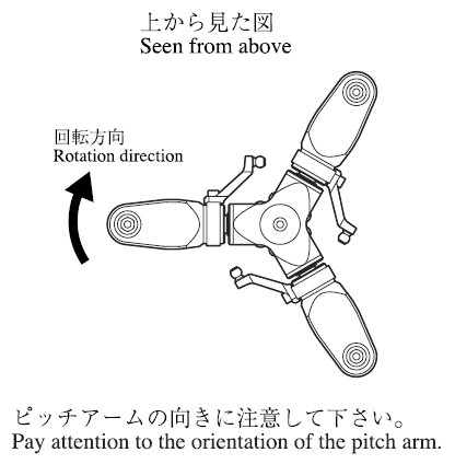
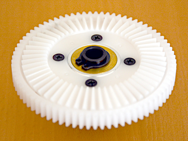
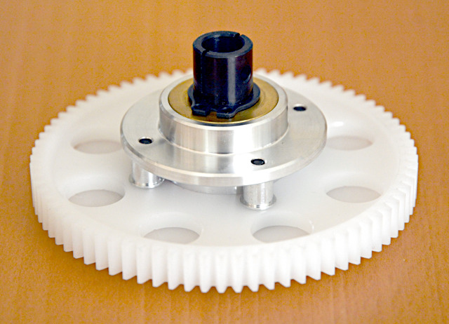
The rotor head is symmetrical but the blade airfoil is not – it is cambered (something like a NACA 2415). As Rüdiger Feil could confide to me, that's not a problem. The three-blade rotor had been originally created for HIROBO's CH-46 and CH-47 models, that is for counter-rotating tandem rotors. Hence I could simply order a set of counterclockwise blades. The rotor head's blade holders are just turned so their pitch arms point in rotation direction (shown for clockwise in the picture).
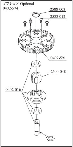
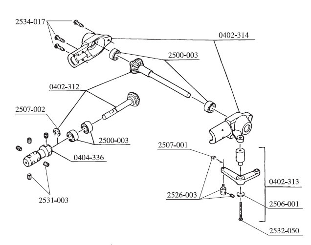
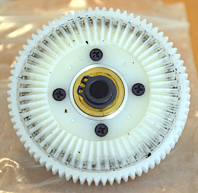
Of course, the freewheel (aka autorotation clutch) has to be reversed. According to this spare parts drawing, that should be possible but – with my tools and skills – I was not even able to dismantle the shrink-mounted parts (0402-016) and wouldn't have been able to re-mount them, either. Rüdiger Feil did that for me in his workshop.
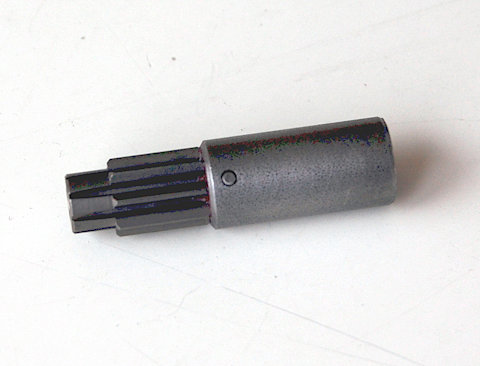
The pinion has a threaded stub by which it is screwed into a clamping sleeve for the motor's shaft journal. Maybe both parts are available as different variants (cog modulus, shaft diameter) and that's why they are separate parts screwed together, or the pinion is simply the original one from the kit. However, a motor turning clockwise matches a right-hand thread while a motor turning counterclockwise would unscrew it. Because of that, I not only dripped Loctite into it but also drilled through and dowelled it.
If the main rotor's sense of rotation is reversed, the tail rotor's is reversed as well. The tail rotor blades have symmetrical airfoil so they can be mounted either way. But the tail blade holders are not symmetrical, and the tail pitch plate assembly isn't either, so they can't be flipped over like those on the main rotor. That's not so bad, though, because the tail rotor is rigid and has no cyclic pitch control.
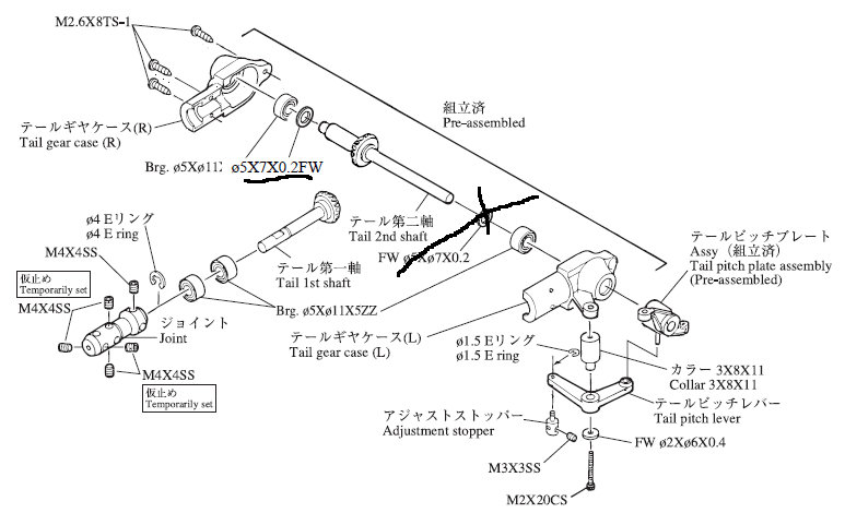
Still I had another bold idea: Perhaps it is possible to turn the bevel wheel on the tail rotor shaft ("2nd shaft") and put it on the other side of the bevel wheel on the drive shaft ("1st shaft") like drawn in here – the sense of rotation would stay unchanged then.
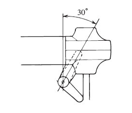
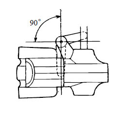
For good measure, another wangle would be corrected: Because the tail rotor had been relocated to the left side (compared to their basic scale kit), HIROBO had to change the tail pitch lever's neutral position by 30°. Only this way the tail rotor blades have the pitch angle they need to blow to the right, to the tail gear. Geometrically, this is not exactly a good arrangement but just another necessary wangle. If the tail rotor's sense of rotation could be retained, the tail rotor blades would now have the opposite pitch angle and the lever would be in the position actually intended – like on the HIROBO Lama (right picture) where all is correct.
Not even Rüdiger Feil could help here, that is he couldn't relocate the bevel wheel because it is made from plastic and injection-molded directly onto the steel shaft ("2nd shaft"). So the slanted lever and the blade holders being the wrong way round will stay unchanged, that is uncorrected. There's one benefit in reversing the tail rotor's sense of rotation, though: On top, the blades turn backwards now so they cut through the main rotor's wake in its direction and not against it. That's how it should be (in most if not all cases) because the tail rotor is more effective and less noisy then. So one – yet unmentioned – consequence of the "wangle" is fixed now. (By the way, the six drawings are borrowed from the instruction manuals for the HIROBO S-300 and Lama, respectively.)
Assembly
Once it was clear which modifications are needed to reverse the main rotor's sense of rotation, they had to be incorporated into the assembly process – in addition to the modifications for the three-blade rotor, which are specified in a separate manual. Electric conversion simply meant leaving out all parts specific to a glow engine drive and installing the electric motor with the special parts made for that by TMRF.
Drive, Main Rotor, Controls
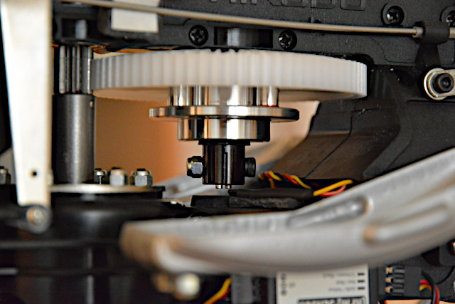
The pinion, dowelled on the clamping sleeve, has to be put on the motor's shaft journal so that its teeth are exactly at the same level as those of the cogwheel – that has to be measured and tested before installation. The black thing in the clamping sleeve is the setscrew which fixes the sleeve in place. The motor's shaft journal was flattened for such a screw and the shaft journal's length (23.5 mm) was adequate – no further treatment needed.
The motor's sense of rotation can be reversed by (1) interchanging two of the three leads to the ESC or (2) setting an ESC parameter – just as you like.
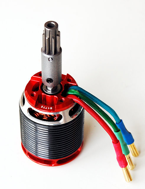
The KONTRONIK Pyro 600-09 (kv 930) is an amazing motor and most warmly recommended by Rüdiger Feil. It weighs only 235 g but can yield up to 2 kW power (and costs 1.06 €/g). It's very efficient (94% maximum efficiency) and it can spin at up to 30,000 rpm but will be operated at only 15,000 rpm in this case. Of course, that is no reason for a discount (just kidding).
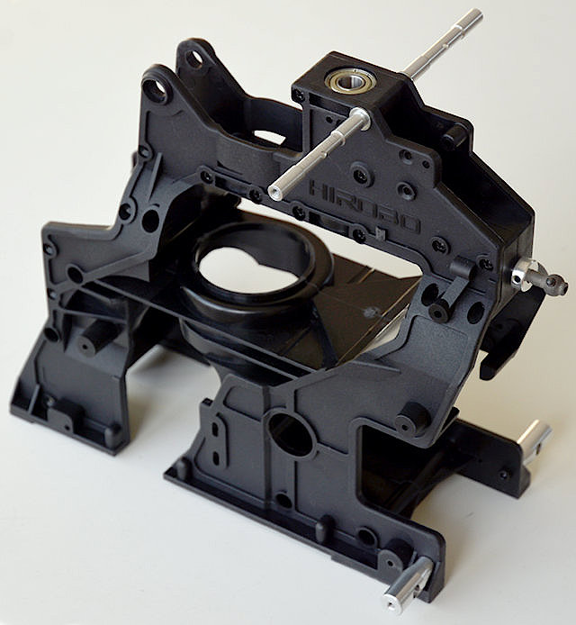
The main frame is composed of two very precisely injection-molded, mirror-inverted plastic parts, which require only very little dressing and buffing. Five ball-bearings are inserted into one of them and then both halves are tightly joined up with quite a few screws. All of these screws are neatly enumerated in the instruction manual lest we forget but one of them. A very small warpage (probably due to cooling down after the injection-molding) has vanished now and the frame is absolutely straight and very solid.
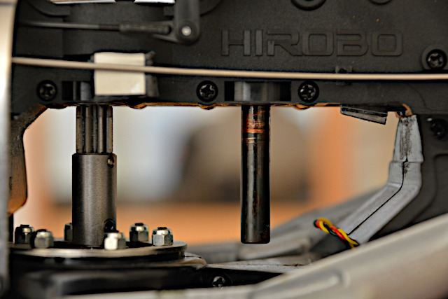
On the frame's rear (on the right in the picture) protrudes the journal of the tail rotor drive's shaft. Not visible here, the bevel gear pinion is already fitted to it.
The two aluminum stubs on the frame's lower rear side and the molded stubs at the tail rotor shaft's level are mounting points for the tail boom struts. The long aluminum rods on the frame's top will later hold the "scale" dummy fuel tanks.
The "bell" in the frame's center is actually the cooling fan shroud for the glow engine – here it lends itself to be the electric motor's mount.
Here is the motor – properly centered and absolutely secure – bolted to the steel sheet disks especially made by TMRF Rüdiger Feil. The stub on the pinion's top is guided in a ball bearing so the gear's tooth backlash is correct.
Bolted on top of the bull gear is the tail rotor drive's bevel bull gear, exactly aligned as well. The autorotation clutch – "reversed" here – is bolted together with the two bull gears so in case of autorotation the tail rotor will not spin (alas – I'd prefer it would).
Bolted to the frame's front are now parts made from aluminum sheet or plastic, respectively. They are meant to hold the servos in special trays and the rest of the R/C gear as one sees fit. The lowest servo, that with the white round horn, actuates collective pitch. For the three-blade rotor, the pushrod has to be mounted in the lower hole of the big aluminum lever. I also reversed the servo's horn and sense of rotation, simply because I deemed that better in this case, but it wasn't (see below).
Between the big aluminum lever's upper right end and that of its counterpart on the other side is an axle. At its left and right end sits one roll-control lever each, and centered on it (between both aluminum levers) sits one pitch-control lever. So the whole thing is the mechanical mixer mentioned above, or it's several mixers, for that matter.
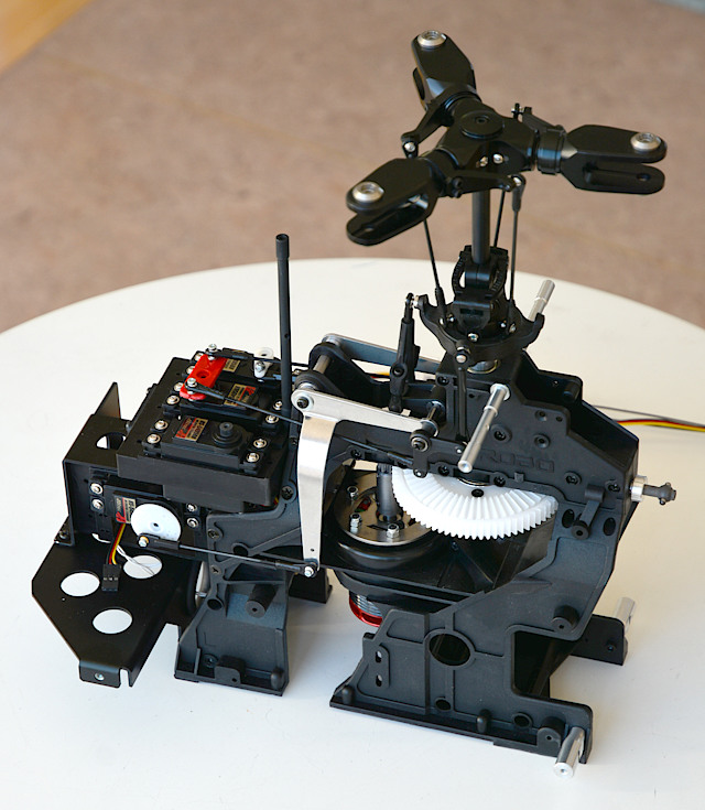
I hope the swashplate linkage is visible here, as well as the swashplate driver (called radius arm by HIROBO), the pitch-arm linkage for counterclockwise sense of rotation, and the rigid three-blade rotor head. The servo without horn on the left side will later actuate the tail rotor's pitch by means of a Bowden cable.
The servo horns are not yet bolted here so I can easily take them off. The linkages are adjusted by turning the ball links on the pushrods, and instead of pulling out and pressing in the balls I prefer taking the horn off. To adjust roll control, the ball links have to be taken off the horn in addition.
It's possible to put the whole thing sidewise on a desk without damaging the linkages – they are protected by the parts protruding sideways.
The instruction manuals specify the required lever arm length for every single servo, in fact different values for the three-blade rotor. HIROBO puzzled things out to a T and had to wangle again so all linkages are clear from each other and don't rub against anything.
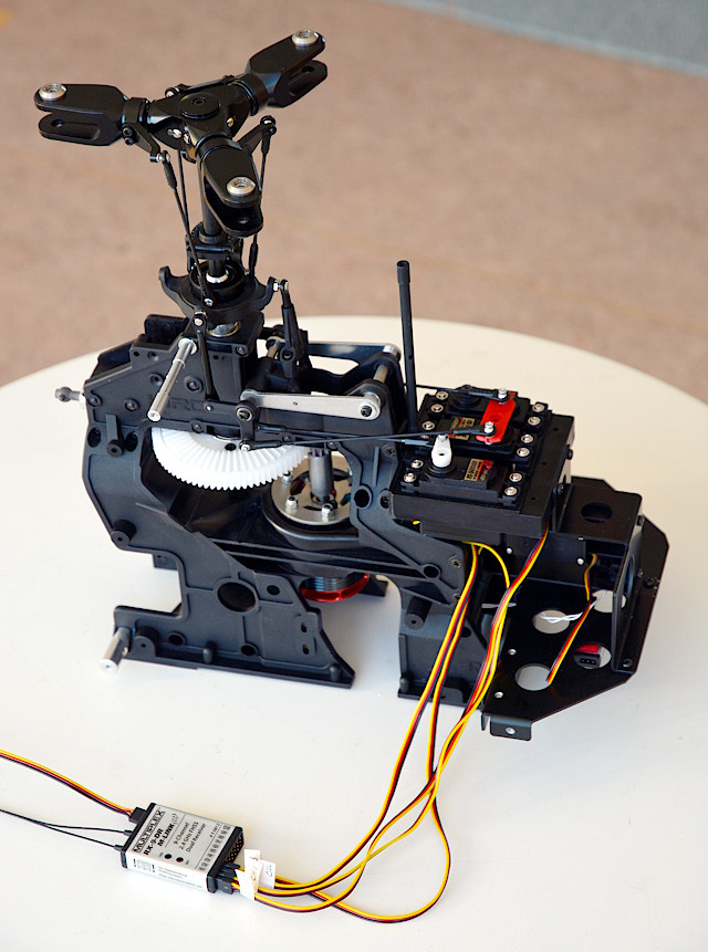
The servos are plugged into the receiver to enable adjusting the linkages. Later they will be plugged into the "flybarless" system (Microbeast) and the receiver is connected by one lead for composite signal. The white twisted lead on the base plate belongs to the telemetry temperature sensor on the motor.
The black vertical rod behind the servos and the lugs on the base plate's left and right side will later hold the cabin.
The big round hole sideways through the whole frame is nearly exactly below the main rotor's center (just a bit further fore). I intended to keep it clear and later use it to balance the completed helicopter, but then the batteries sidewise on the landing gear were in the way.
Here you see that standard-size servos are needed. Rüdiger Feil said that "no super strong or fast" ones are needed but "just good digital standard servos" would be sufficient. Then I figured the Hitec HS-5495BH would be just right. Even though they are inexpensive (at least they were), they are good and strong and very precise. They have no metal gear (but Karbonite), but this helicopter is electrically powered and will not be shaken by a glow engine, so that's OK. And perhaps in 1995, when this model came out, even the best servos were not as good as these modern ones. In any case, their actuating power should suffice.
Tail Boom and Rotor, Landing Gear
Looking like a helicopter already. The rotor blades and the electronic equipment are still missing as well as the cabin and the dummy tanks.
However, the rotor drive and the controls are working properly. They are adjusted for now, just the blade angles may need some fine tuning after final assembly.
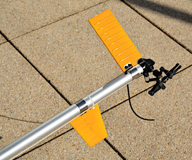
I like the varyingly shining metal parts so I left them unpainted. The white-plastic stabilizers have been painted all (Camel) yellow for good visibility and because I like that color.
The tail rotor linkage is a 1.25 mm piano wire in a thin steel pipe, which is shielded by a quite thick and soft plastic pipe. That is all held in one single lug on the main frame's side. The pipe's end and the servo's horn are quite far apart from each other but the wire is rigid enough to act as a pushrod. The distance is even good for a soft curvature.
The piano wire had a Z-bend for the servo horn but I don't trust this solution, at least not in this case where the linkage is vertically tilted and the small-diameter hole could wear out soon under the big linkage loads. The hobby shop had a clamping sleeve with a threaded stub for a ball link, which is advantageosly at the servo horn's lower side now. The sleeve has been secured with Loctite for the set screws and epoxi for the wire.
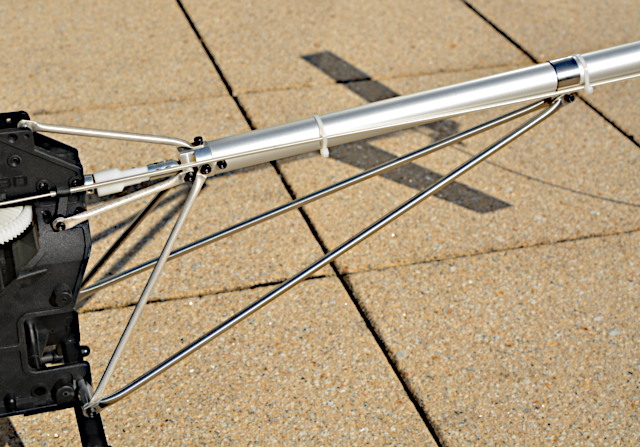
The tail boom truss comprises five short aluminum tube braces to hold the boom's root and two long stainless-steel tube braces to support the boom's middle. The boom is just an aluminum tube with a piano-wire shaft running in its center.
The hub has to be adjusted so the thin shaft is straight and not bent. That worked out really well by shifting the hub into the correct position on the shaft and fastening it with four set screws.
The five short braces have to be bolted to the boom's root and the main frame so that the boom is in the right position and the tail rotor shaft is horizontal. That worked out not so well in that the boom is turned a bit as soon as the screws are tightened while all was perfectly aligned with the screws tentatively set by hand.
Now the tail rotor shaft is pointing a tiny bit upward, but I think that's not a problem since in flight the helicopter is tilted to the left, anyway, and the tail rotor is even vertical then. In this picture you can hardly make out the tilt.
The tail rotor linkage is strapped to the boom with zip ties what makes it a bit curvy, but again I think that's not a problem since linkage friction is still moderate and the strong servo can cope with it.
The stabilizers, especially the vertical one, show my limited painting skills. I was not able to control the spray can's nozzle smoothly so there are some sags and hangs and runs. Oh well, this will be a stand-off scale model anyway, now maybe even stand-way-off.
But most important for me, the horizontal stabilizer is slanted 30° upward like on the original helicopter. The tail rotor will turn clockwise so the pitch arms are trailing (not leading) but I knew that in advance (see above) and it's OK for me.
The landing gear is much like the original but without diagonal struts and with wrap-around skid holders. Both features could make for trouble when the helicopter is skidding forwards in an autorotation landing. However, that might be more like a crash, anyway, so they are irrelevant.
There should be sprung struts with different spring stiffness for the different loads on the front and rear struts. The stiffer struts should be labeled but they aren't, and I just can't distinguish them. I'll have to test and permute them once the helicopter is complete.
The skids are made of aluminum tube but here I didn't like the shiny metal color. I painted them semi-matt black so they blend in with the rest of the landing gear which is all black.
In this state of construction the helicopter has been test-run with a small drive battery. The ESC is set up as a governor and the set rotor speed has been defined already. After a short break-in of gears and bearings all ran smoothly and with low friction. Amperage – as indicated by the ESC's telemetry – is a measure of friction moment and suggests even 96% overall (main and tail rotor) gear efficiency – beyond my expectations.
Cabin, Dummy Tanks, Tail Rotor Blades
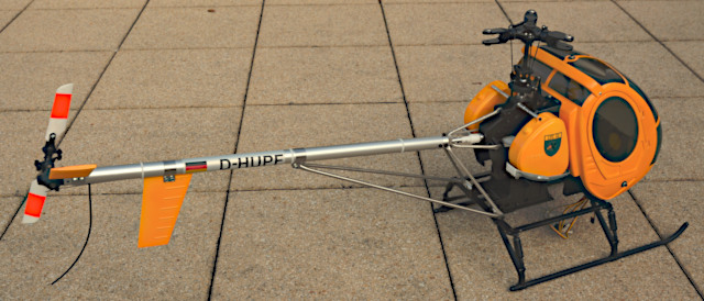
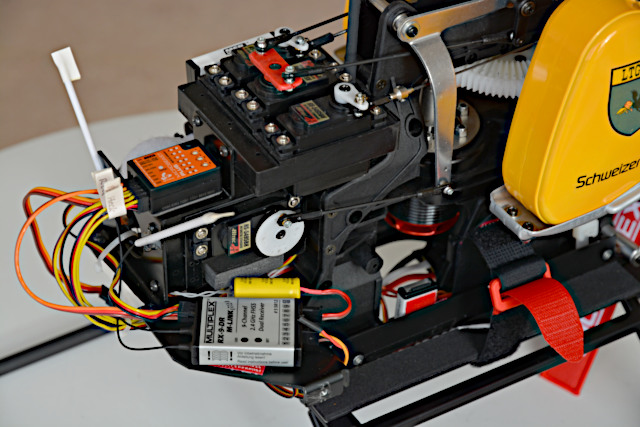
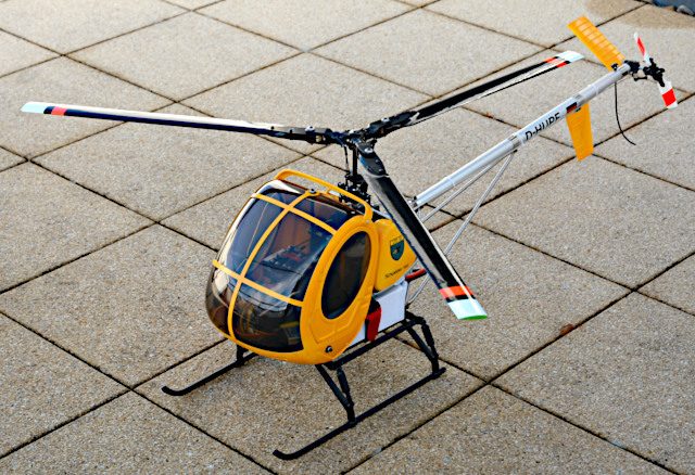
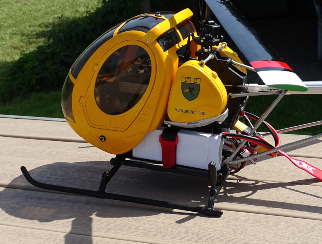
Looking even more like a helicopter. The main rotor blades and the electronic equipment are still missing and the battery placement is not yet settled.
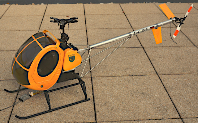
Most important for me, this model looks really "scale", more than any other S-300 model I know of. I like this type because it looks so cute to me. Yellow cabin, tanks, and tail feathers as well as silver tail boom and black landing gear turned out after my fancy. I'm really pleased.
Moreover, all is well visible even when it's overcast. To be "scale", the tail rotor blades would have to be square and all red with one white cross stripe. But the red film cross stripes on the tapered white plastic blades are not too bad, either.
I made it this way because it would be hard to put the film firmly onto the rounded blade tips and roots. Then, the name HIROBO in raised letters is molded into the blades, just in front of the trailing edge and close to the root, so the film wouldn't stick there, despite a bit heat from a covering iron.
Registration, flag, and emblem are printed on special transparent adhesive film for color laser printers. Only black is really opaque while all colors are more or less transparent. It's still acceptable, though.
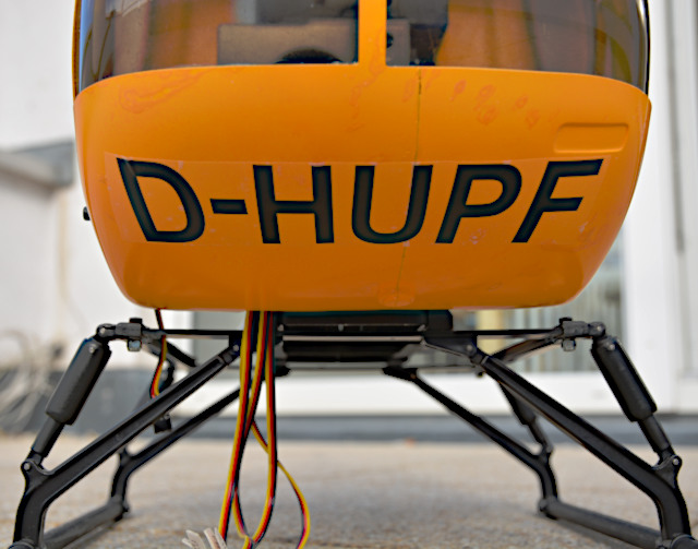
The film is just meant for a white ground, but the black registration on the cabin's front bottom is good even on the yellow ground. The lettering is curved so it fits the cabin's shape.
By the way, the D stands for Germany and the H for helicopter. Hupf is a German word and means something like hop in English. I thought that's appropriate since it's what this cute helicopter will do.
I didn't bother to prepare the cabin for painting (actually spraying with a rattle can) because I wouldn't be able to do it well in any case. You see the seam of the fiberglass halves and a lot of dapples where I patched scratches in the paint. Other than to the plastic parts (tail feathers, tanks, cabin doors), the paint doesn't adhere well to the fiberglass parts, which is why they should have been treated with a primer.
Well visible is the landing gear's structure with four equal legs and sprung struts. The main frame's bottom plate is still missing.
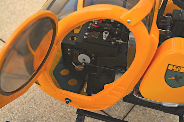
The cabin panes are vacuum-molded and have to be cut along a mark-off line. That turned out to be quite hard because the transparent plastic is quite thick and the cabin pane is quite convex. I managed to cut it reasonably well only with small tinsnips.
To let the cabin look better and hide the innards, the cabin and door panes have been tinted inside with a spray paint called "Smoke".
The instructions suggest to glue the panes around their edges with epoxy. A clubmate recommended "Canopy Glue" instead, which is indeed far better for the prupose. The cabin pane was glued on its upper edge first. Then it was tightly pressed into the cabin and glued on its lower edge. Finally, it was glued along both sides.
The instructions suggest 0.5 mm or 1.0 mm thick double-sided adhesive tape for the window bars, but I would advise against using it. The cabin pane is such a tight fit that there is no room for any tape. I just didn't glue the bars, and even if one of them would break I could simply mend it with Canopy Glue.
The "spoiler" on top of the cabin has been screwed on and additionally glued with Canopy Glue to prevent tilting.
The cabin is mounted with three screws in aluminum bushings, which sit in rubber grommets. I managed to insert the grommets into the holes in the cabin by piecemeal pushing their inner lips into the holes with a small screwdriver.
I even managed to use the supplied door hinge pins, which look like the things used to attach a watch strap to a watch. Anyway, I put them into the holes in the door and pressed the pins with a cutter knife on each side. When they slid into the cabin recess with the corresponding holes (drilled before) the knives were pulled out and the pins snapped in. Of course, they can't be taken out again.
The door cutouts in the cabin had to be widened a bit around their upper half to make room for the door window panes. That has been done by grinding with a Dremel tool. The small jut is where a magnet has been glued in, corresponding to a magnet already in the door.
A close look shows some dings and scratches in the paint. They should be patched with a small brush but they are hardly visible from "stand-way-off scale" distance.
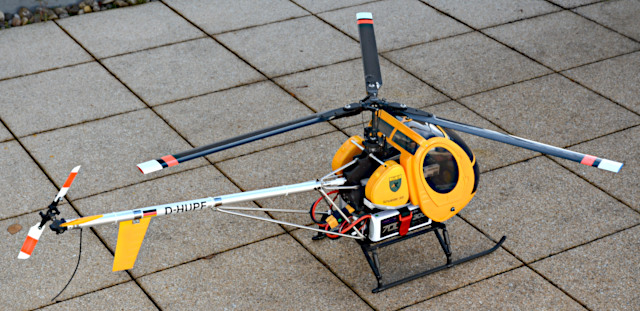
This state of construction is interesting because the helicopter is shown in its final look, but it is really important because the battery placement can be settled now. The completed cabin is quite a weight in front of the main rotor, and it shows the restricted room to place one or two batteries in it. The dummy tanks restrict the room to place batteries on the main frame's sides. In the Web forum threads, some owners put two batteries on the left and right side inside the cabin. Others reported that they had to put two batteries on each side of the main frame or one battery under the main frame to get the C/G in the correct place. The latter seemed to be the case here.
Batteries and Electronic Equipment
The next step was finding out how to get the C/G in the right place. First, the receiver battery got its "logical" place on the right side of the equipment plate (my term). On its back side, the bracket included in the kit (for a switch) was used to tie a battery strap. The place was padded with thick and thin foam rubber to protect the 2S LiPo battery from dents and dings.
The receiver battery as the only substantial weight in the helicopter's front was put into its place and the cabin put on. Now several things of different weight were strapped under the helicopter's bottom to balance it. 450 g weight had to be quite far in the front, protruding under the cabin. 750 g still protruded a bit but 900 g were just flush with the cabin's trailing edge (and the landing gear's leading edge).
That effectively settled the battery question. I intended to use our regular supplier's 6S standard batteries and his 5000 mAh (765 g), 5300 mAh (800 g), and 5800 mAh (870 g) batteries are not heavy enough. I know that sounds ridiculous but in this case the battery has to balance the helicopter in the first instance. Then again, if the battery (or two of them) were in the cabin they had to be extremely lightweight (low capacity, high C-rate) and the C/G would be still too far fore. Anyway, that's how I see it and that's why I decided for the 7000 mAh battery, which weighs 937 g.
Now I made dummy batteries from cardboard, one 6S and one 3S, to see how they could be attached to the helicopter. The 6S had to hang under the bottom and would be prone to damage there. But the 3S fit so well on the main frame's side and in the cabin's rear that it seemed to be purpose-made for it. So I decided for two 3S 7000 mAh batteries, which together weigh even 1000 g and hence belong in the middle of the landing gear.
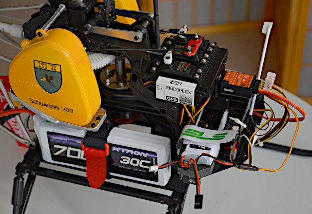
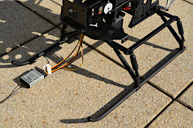
Two unused knobs for screws on each side of the main frame are perfect for fastening battery supports made from plastic angle section. These had to be cut to length and notched to fit and lie on the front and rear landing gear cross bars. Spacer sleeves are needed lest the batteries abut against the slanted dummy tank supports. Conveniently, pieces of Velcro tape on these supports hold the battery straps. These and anti-slip layers of thin foam rubber on the battery supports hold the batteries safely in place.
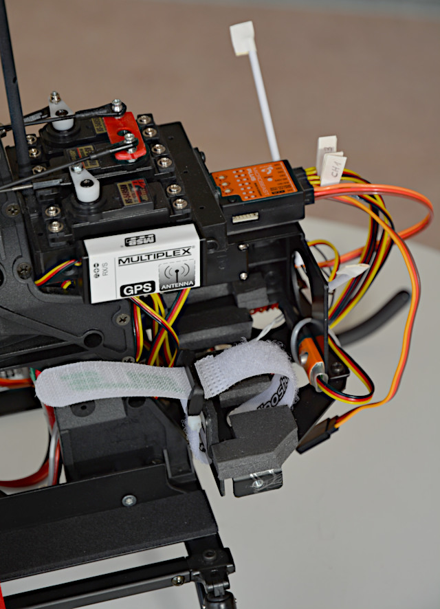
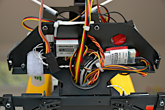
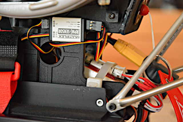
By the way, the GPS telemetry device is installed just experimentally (see below). The "receiver battery" is directly connected to the 3-axis gyro system (Microbeast) to have low resistance to the servos. The receiver (on the other side) is connected to the gyro system via one lead only for both serial data signal and power. The orange shrink-wrapped thing next to the receiver battery is a voltage regulator for the telemetry sensor bus.
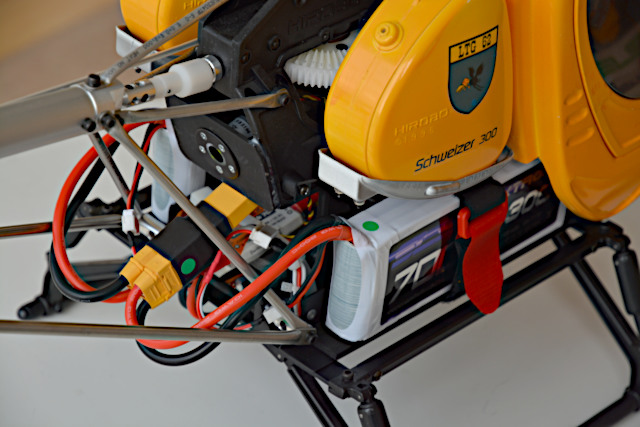
A 30C battery is well enough as the helicopter will fly at about 4C only. Still these batteries come with massive cables and XT90 connectors, just to be on the safe side, even though XT60 would suffice in this case. Anyway, an equally massive serial adapter (in black shrink wrap) is needed to connect the two 3S batteries giving one 6S.
The green dots on the adapter's side and on the battery are there lest I confuse the connections. I charge both batteries together as one 6S so I need a balancer Y-cable where the batteries are connected in the same order as they are on their power cables. And in the helicopter is a telemetry cell-voltage sensor which likewise has a Y-cable on its end for the batteries' balancer connectors (and a green dot on one connector).
Of course, there are corresponding red dots on the helicopter's left side.
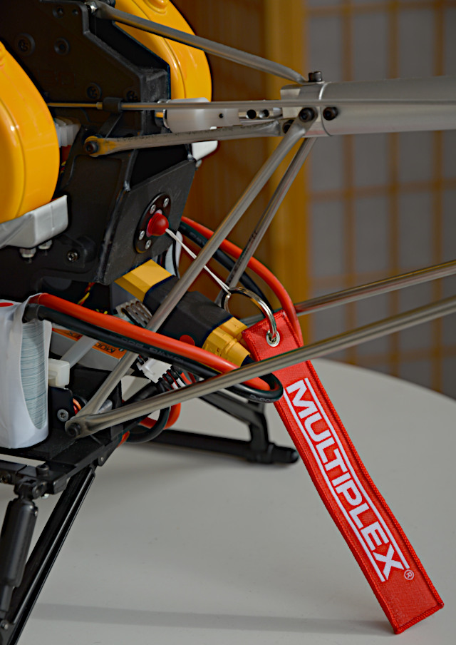
Above the black/yellow XT90 serial adapter is the so-called Safety Switch. In the previous picture, its cylindrical body (with a white label) can be seen projecting into the space below the tail rotor shaft in the main frame. I had made a cardboard template and jigsawed a piece of plywood that fits the frame's outline and has a hole for the switch. Inside around the hole the plywood was doubled with a plywood ring so the switch could be fastened with five small wood screws. The plywood switch holder had been painted black and glued on (with Canopy Glue) before.
In the switch's center is a transparent ring, which is an annular light. In the previous picture, the light is green (hardly recognizable) meaning "power system armed". In this picture, the red magnet (with pennant) is inserted so the light is red meaning "battery connected". Of course, the light is off when the battery is disconnected, no matter where the magnet is.
The switch is connected to the orange/white thing (strapped with a big zip tie) below the XT90 serial adapter, which is the AntiFlash device. It's the actual switch and powers the Safety Switch, which would show no light if something would be wrong. That's why I preferred it to anti-flash XT90 connectors, which would have been lighter and cheaper.
After the first flights, the cell-voltage sensor has been relocated from the equipment plate and strapped on top of the orange/white AntiFlash. That's actually the right place for it and it should have been put there in the first place.
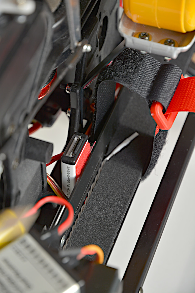
This is the battery support on the helicopter's left side. The white thing (with the twisted white cable) in the anti-slip foam-rubber layer is a temperature sensor for the battery. There is another such sensor strapped to the motor housing.
The battery strap, which is actually a strip of Velcro tape, is conveniently attached to the slanted dummy tank support where a Velcro counterpart has been put on.
The box attached (with red Velcro tape) to the battery support's inner side is named the FlightRecorder. It logs (or records) all the data that are sent on the telemetry sensor bus. After a flying day, I take the Micro SD memory card out of it to transfer the recorded .csv files to a computer for analysis.
The box has been placed next to the main frame's opening for better access to the memory card. It's a bit inside the cabin but still accessible when the battery is removed.
Between the battery support and the main frame run two cables from the ESC: the servo cable to the receiver and the telemetry sensor bus cable that goes into the FlightRecorder. From there it goes to telemetry sensors under the bottom of the equipment plate.
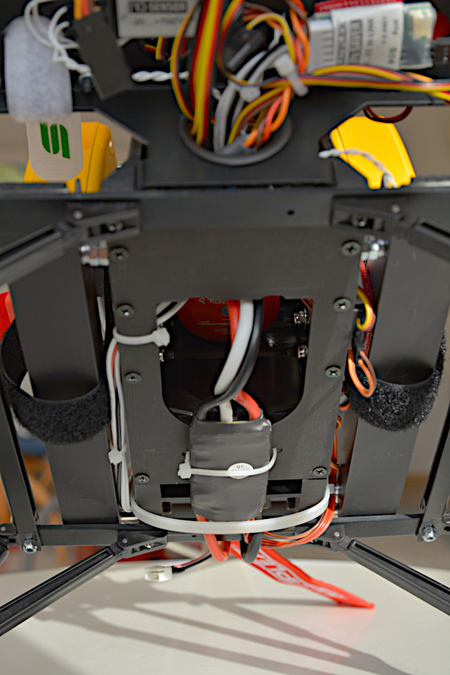
This is the helicopter's bottom where the ESC is strapped (with a zip tie) to the bottom plate. I didn't find a better place for it even though I won't put the helicopter on floats and do water landings now. Anyway, the drive components are all centered on the main frame and the thick cables are bent not too much. The huge zip tie around the ESC is actually for the AntiFlash device (see above) and is just a side benefit here.
After the first flights, the ESC was turned around (upside down) in the hope of lowering its working temperature. That didn't work out, so the ESC was fastened on edge then to let the cooling airflow to both sides, as recommended in the instructions.
In the middle of the picture, the three motor cables come down through the bottom plate opening and go into the ESC. A red and a black cable go from the ESC's other side up into the AntiFlash device, making a U-turn.
On the right side in the picture (left side of the helicopter) are the ESC's servo and telemetry bus cables between the battery support and the main frame. On the other side are the seven cores of the cell voltage sensor cable (for the 6S battery). After the first flights, the cell voltage sensor has been relocated to the rear and this actually unnecessary cable bundle has been removed.
In the foreground (upper part of the picture, blurry), a tangle of cables comes out of a round opening in the main frame's front. These are all the cables mentioned so far coming from behind, and the servo cables.
A piece of fuel tube has been cut open lengthways and put around the sharp edge of the round opening (and in other places as well) to protect the cables from fraying.
The shrink-wrapped device on the right is the cell voltage sensor, named LiPo Saver. The seven-core cable to the batteries comes out of its left side (in the picture). Later, this actually unnecessary cable could be removed after the cell voltage sensor had been relocated to the rear.
The device on the left is named the temperature sensor but is just a box with electronics. The two twisted cables to the actual sensors (on motor and battery) come out of its left side.
On the left side is the white Velcro strap for the receiver battery.
The receiver went to the equipment plate's left side so the cables for the serial data signal and power as well as for the telemetry sensor bus come out in forward direction.
The two antennas come out there as well and are neatly threaded into the white plastic tubes, which have been glued (with Canopy Glue) to the front of the gyro support (where the Microbeast sits on top). They are secured with pieces of white fabric adhesive tape.
Only the ESC (but no servo) is connected to the receiver's other side, and the cable's red plus core has been removed from the plug to disable the BEC. The yellow capacitor is connected anyway to smoothen potential voltage spikes from the servos in case the BEC would be used.
The collective-pitch servo linkage had to be modified when the gyro system was set up. It turned out there was not the required pitch range from -5° to +15°. The pushrod stayed in the lower hole of the big aluminum lever (as advised in the instructions for the three-blade rotor), but the servo horn had to be inverted (the pushrod at top, like in the instructions) to have enough pitch range. Additionally, the ball link was moved to a hole a bit more outwards because else the servo would need more than 45 degrees travel. The pushrod had to be lengthened a bit to prevent the mixer axle from touching the main frame in the low pitch position. Consequently, all three pitch rods had to be shortened but that was done later when the blades' pitch angles had to be adjusted, anyway.
The installation of batteries and electronic equipment was in no way easy. In fact it was a difficult process that couldn't be planned but had to be undergone step by step. The components bound for installation were given in the beginning but not the places where to mount them. In this sense the process turned out even all right, all components falling into place one after the other.
Main Rotor Blades
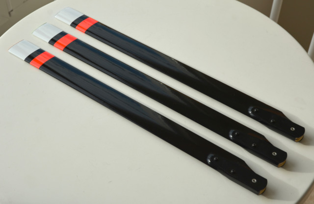
The main rotor blades had to be prepared for mounting. The wooden blades are neatly covered in black shrink film. Oval pieces of it have to be cut out at the blade root's top and bottom.
There are three pre-drilled holes for aluminum bushings, which have to be glued in with 30-minute epoxy. Likewise, one black sheet-metal plate each is glued on the blade root's top and bottom. Three holes in the plates pefectly match the bushings in the pre-drilled holes. Finally, the plates are clamped by two screws, washers, and nuts in the outer holes. The inner hole is for the blade-holder screw.
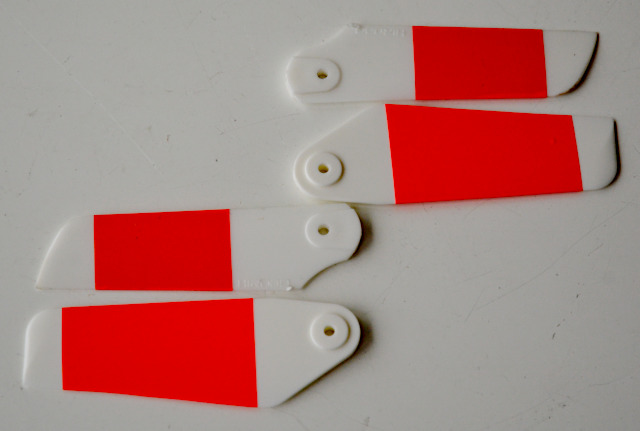
The white and red tip stripes are film covering and run on top from the trailing edge to the leading edge and a bit around it. I just fancied them this way, that is their widths and colors.
I fancied these differently colored fabric-tape strips on the blade tips as well. Of course, my intention was to see the blade tracking and my assumption was that the tape will firmly stick to the tips despite centrifugal forces. Both was not sure but I was quite confident. (Result: no, yes.)
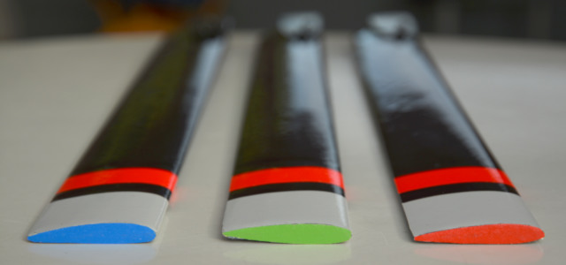
The blades seem to be very different in airfoil and pitch angle but they aren't. The shrink film cover has been made flat on the tips and that made for the somewhat skewed outline. I just stuck a piece of tape on each tip and cut around their outlines with scissors.
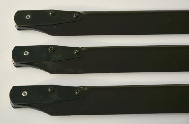
Still the pitch angles have to be adjusted after mounting them to the rotor head. After all, wooden blades can be not as uniform as metal or fiberglass blades and may develop some distortion.
The blades are balanced already by applying pieces of clear adhesive packing tape to their bottom side close to the tip. The "blue" blade is the heaviest so it got no tape. The "green" blade is a little bit lighter and got about 50 mm tape, and the "red" blade as the lightest one got even three plies of tape.
The clear tape is just so hard to show in photos that I rather show the blade roots, which are hard enough to show. You see edges of the shrink film (left), the bushings for the blade holder screws, and the top and bottom plates bolted together with two screws each.
Mounting the blades had been deferred until the battery placement was clear, the electronic equipment was installed, the 3-axis gyro was set up, and the drive with ESC/governor was set up and tested. Only then they were mounted and their pitch angles adjusted. The blades have been weighed before that, just to know that they contribute 322 g (11.4 oz) to the overall weight (the rotor head 219 g / 7.7 oz).
Completion
Now that is a helicopter! The batteries are connected and the main-switch magnet has been removed so the helicopter is standing ready-to-fly on my roof deck. Of course, the transmitter is on and power cut off.
All-up weight (AUW) is now 4.5 kg (159 oz or nearly 10 lb), even 0.3 kg (11 oz or 0.7 lb) more than I had expected. Of course, that is my treat because I chose the big 7000 mAh battery, split it in two, and use a serial adapter with massive XT90 connectors.
Anyway, the batteries have to rest right smack in the middle of the landing gear (or up to half an inch more forward) to have the C/G exactly under the rotor mast. That was my main reason to choose the big batteries, the longer flight time being a side benefit.
I'm looking for kind of black socks to hide the batteries while I'm quite happy with the tangle of red and black cables and yellow connectors. These colors correspond to the other colors on the model.
The main rotor pitch angles are adjusted as well as in any way possible. Since the pitch rod length can be adjusted only in steps of half a turn of one ball link, one blade has still 0.2 degrees more pitch than the other two whose pitch angles happen to be equal.
The 3-axis gyro system (Microbeast Plus) had been updated to firmware version 5 and upgraded to the ProEdition. So all settings could be done on a computer connected via an USB adapter (what is intuitive for me), and even a rescue function (bringing the helicopter back to upright attitude) could be activated. All that had been set before completion but was checked again after adjusting the pitch angles. All worked properly – as far as that can be seen without the helicopter up and running.
Flying
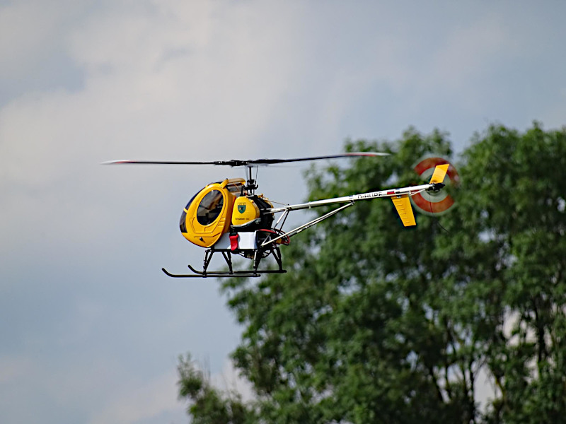
"Lil' Boy" just flies. On November 10, 2019 we had only 1°C (34°F) and hoarfrost so my fingers were frozen (and I had the jitters). I was lucky enough to have the maiden flight done for me by our club's heli expert. He looked over the heli, took it off, and set it down shortly to reduce the tail gyro gain (which I had inadvertently set a bit too high on the transmitter). Then he put the heli in hover flight 6 feet high and took his thumbs off the sticks to show me that it hovers hands-off. The picture shows Lil' Boy after the successful maiden flight on the setup bench, in good company of the clubmate's helicopters:
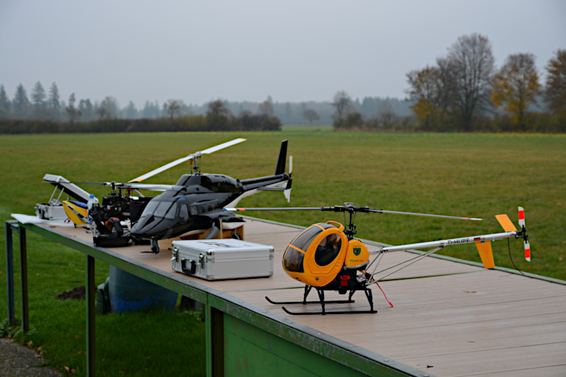
My part had been to correctly set up and adjust the helicopter and obviously that turned out all right. Especially the blade tracking was as good as it can get given corrections can be done only in steps of half a turn of the pitch rod threads. The blades are well balanced: the heli shaked a bit when running up through 400 rpm (spreading out the blades) but then had no visible vibrations at all on the ground as well as in flight.
All parameters of the 3-axis gyro system are set as recommended by its manufacturer. Even the tail gyro gain recommendation was spot-on. There seems to be no need to adjust anything except as a matter of preference. For instance, expo is set to 50% on all three axes. The expert pilot said it's too much for his taste (he's flying 3D) but I'll leave it that way. The gyro system as well as the transmitter may be still set up for three different flight modes, just for convenience (and in addition to the mandatory autorotation mode).
Last but not least, the maiden flight proved the counterclockwise conversion feasible. It proved it successful as well since there was no tail wagging due to turbulence on the horizontal stabilizer (only due to too high gyro gain). The not-so-good tail rotor pitch linkage arrangement is not caused by the counterclockwise conversion but by HIROBO simply relocating the whole tail rotor from the right to the left side without reversing its sense of rotation.
The "test pilot" merely complained about the tail rotor seeming rather weak, that is there was no obvious snap-in when a yaw had been ended. However, that was known in advance from experiments in the simulator where the tail rotor's power was just enough at low main rotor speeds. It may be regarded as part of "scale", though, that the original Shuttle tail rotor is rather "soft" on the heavier Schweizer 300, where it spins even slower due to the slower-spinning three-blade main rotor.
In about 7 minutes of activity, 2450 mAh were drawn out of the battery, that is 35% of its nominal capacity. There was just running on the ground, then hovering at 1420 rpm and at 1520 rpm. It was a 350 mAh/min average battery drain making for exactly 15 minutes flight time if only 75% of the battery's nominal capacity are drained. To be on the safe side I'd assume 29.5 A drawn in hover flight at 1520 rpm (27.5 A at 1420 rpm) meaning 492 mAh/min (458 mAh/min) battery drain and 10.7 minutes (11.5 minutes) flight endurance.
Consequently, I've set the alarm timer in the transmitter to 11 minutes to have a timely signal that draws my attention to the telemetry warnings following soon (see below). But now I go exclusively by this timer, which beeps before elapsing (in the last 5 minutes every minute, in the last minute every 10 seconds, in the last 10 seconds every second). The ESC/governor is set to slowest possible runup (on our smooth wooden helipad) so it needs even 40 seconds to 1600 rpm. Then, if I land the helicopter in time after 11 minutes, the battery's idle cell-voltage is between 3.76 and 3.78 V – more than the battery supplier's recommendation (3.75 V). That's maybe 30% to 35% charge remaining, so it's far on the safe side and flight time could be safely up to 13 minutes. But for me, 10 minutes net flight time is enough and it's easy on the battery.
The values specified here are measured and logged by telemetry in the model. It showed as well that battery temperature increased by only 10°C (18°F). It would have increased further in a longer flight but in no way critical. Motor temperature went up (from 1°C/34°F) to 38°C (100°F) in flight and up to 47°C (117°F) after it when the cooling fan in the motor was no longer spinning. The ESC/governor went up to 73°C (163°F) and immediately down after flight. But its tendency was still distinctly up at the end of the flight so it had to be monitored to see if a cooling fan is needed for longer flights.
Battery and motor didn't have problems at a moderate 22°C (72°F) summer temperature: The battery goes up to 27°C (81°F) in cruise flight and 32°C (90°F) after hovering for a while, the motor to 54°C (130°F) or 58°C (137°F), respectively, and to 65°C (149°F) after the flight. So there is still no problem in case ambient temperature is high: A LiPo battery's maximum is 60°C (140°F), that of neodymium magnets in a motor is 80°C (175°F) (or in this motor purportedly even 150°C/300°F), and both are not reached.
The ESC/governor did have problems, though. In cruise flight, its temperature was steadily between 84°C (183°F) and 88°C (190°F), but in the subsequent hover an alarm was set off: 100°C (212°F). (Only at 125°C/257°F it would cut off.) That happened no matter at which side it was fastened under the helicopter. The instructions say "air must be allowed to circulate freely around the controller", so it was finally fastened on edge then (see previous picture). Now heat can be given off on both sides. That solved the problem. In strong or gusty wind the ESC/governor did not reach 100°C (212°F) even before, now also in a soft breeze, if only just.
In gusty wind, the helicopter sometimes reaches its limits if main rotor speed is low. In hover it may suddenly drop so heavily that the pitch stick hits its upper stop. In cruise flight, a downwind turn may let it drop like an airplane, and in a turn it needs a lot of pitch like an airplane with high wing-loading needs a lot of power. This helicopter just has a quite high main-rotor disc-area loading (4.8 kg/m² or 15.75 oz/sqft).
In the transmitter, I had prepared three flight modes (in addition to "Autorotation"): "Hover" at 1450 rpm, "Normal" at 1520 rpm, and "Cruise" at 1600 rpm main rotor speed. These turned out to be useful, and the last two even conform to HIROBO's recommendation in the instructions. In fact, 1600 rpm is the best main rotor speed for cruise flight and for hovering in gusty wind as well, at least with this heavy sample of the S-300. It's advisable to use the lower rotational speeds in calm weather only. This way also the tail rotor is always effective enough.
At 1600 rpm in hover flight, amperage draw is 29.5 A on average, meaning about 650 W electric power. In cruise flight at 15 to 50 km/h (10 to 30 mph) forward speed, amperage draw is 23 A on average, meaning about 500 W electric power. Hence flight time is so long and temperatures are so low. Just the ESC/governor, which is rated for 100 A continuous, gets hot, perhaps because it's working at partial load and – as governor – has to re-adjust rotational speed all the time. There are amperage peaks up to 37 A and down to 13 A.
For me as a beginner, the helicopter's flight characteristics are quite comfortable: smooth flight, gentle reactions to control inputs, still good maneuverability with the main rotor and sufficient with the tail rotor. Expo is set to 50% for all three axes and the control throws are reduced (dual rate) to 80% of the values specified by HIROBO on the main rotor and even 60% on the tail rotor, and I do not miss full throws at all.
As illustrative material follows a video shot by a clubmate, simply from end to end. Notabene: After 4½ hours flight time with this helicopter I'm still a beginner so I'm just practicing figure eight, approach with following spot turn, hover, and landing. If you get bored just use fast-forward (and go to YouTube for the HD version).
The telemetry data logged during this flight are diagrammed and discussed below. That's why the video hasn't been shortened – to keep full comparability.
The Bottom Line
… just as a few notes:
- Nice, prototypical model.
- Substantially and accurately built, good quality.
- Still mechanical mixers, but well done.
- Very good electric conversion.
- The main rotor's sense of rotation can be reversed to CCW.
- Alas, the tail rotor does not spin during autorotation.
- With three-blade rotor and electric drive, the model is rather heavy.
- Flies very calm and stable as befits a training helicopter.
- The tail rotor is just powerful enough for the heavy model.
- All in all, the heavy weight is no problem.
That's it, but let me add a few thoughts:
Batteries
There is an original HIROBO electric conversion kit (with an 890 kv motor) for their Shuttle since this trainer has a main frame that lends itself to putting the drive battery in its bottom. The conversion kit offered by TMRF Rüdiger Feil for the Schweizer 300 is for the motor only and leaves the decision for a battery and its placement to the customer. That's no wonder since there is just no perfect or at least suitable place for one battery and only two options at all. That's why there seem to be two different lines of thinking in the Web forums.
Most of the posters there put two batteries into the cabin, one on each side, and had to even saw off a piece of the gyro support to make room on the right side. Some even use special LiIon batteries, which are quite short compared to the usual long LiPo batteries and better fit in the short cabin. Still they are quite far ahead of the rotor mast (where the C/G should be) so they have to be (and are) quite lightweight. 5000 mAh seems to be the common capacity and there were some discussions how to squeeze more flight time out of them by using different rotor blades and lowering rotor speed.
That seemed not exactly compelling to me, but this line of thinking was so dominant that I overlooked a few posts which argued for a battery placement behind the cabin, under the frame or on its sides. The shady prospects inhibited me for a long time (one and a half year) until I finally brought myself to just try it out. First I had to finish the tail boom and rotor as well as the cabin to be able to check the C/G. Only then it dawned on me that the battery's weight could make all the difference. There is just no place for it that is half in the cabin and the other half behind it. There must be lightweight batteries in the cabin or heavy batteries behind it – no compromise. I read those Web forum posts again and felt vindicated now.
For me it was natural to decide for heavy batteries: That avoided looking for special ones that fit in the cabin and making room there. I found a natural place for really heavy batteries on the landing gear. 40% more flight endurance is a giveaway benefit, and heavy weight is no problem as I found out by trying in the REFLEX XTR² flight simulator. Everything fell into place now.
There is even a technical advantage of the big batteries in that their C-rating can be lower and then their capacity-to-weight ratio is almost 20% better (7.47 mAh/g for 7000 mAh compared to 6.26 mAh/g for 5000 mAh). Alas, splitting a 6S battery into two 3S makes for more weight (1000 g plus 24 g for the serial connector compared to 937 g, nearly 10% more). That could be avoided in case a big 6S battery is hung under the main frame, but probably not even a small 6S battery would fit in the cabin. Then again, the splitting detriment is more than offset by the better capacity-to-weight ratio of the big batteries. At least I persuade myself of this just to feel even better about the heavy batteries than I do already.
Main Rotor
As mentioned above, HIROBO had originally designed the three-blade rotor for their CH-46 and CH-47 models, and back then they made it mostly from plastic parts. Only later they made it completely from metal parts and offered it for the Schweizer 300 as well as the Lama and Shuttle models. The CH-46 and CH-47 instructions say "First printing February 2004" and the three-blade metal rotor instructions "June 2012". The former was the time when wooden blades were still commonplace and three-axis gyros were just emerging. Those gyros had made the tandem rotor models feasible after all.
Anyway, they adapted the rigid and flybarless three-blade rotor to the single-rotor models only
when three-axis gyros were commonplace, and in the instructions they recommend one:
While flight is possible with a rudder gyro only, a commercially available 3-axis gyro makes
it easier to operate the flight controls.
To emphasize their recommendation they add a warning:
When flying the helicopter without a 3-axis gyro, excessive flight speed may cause the
helicopter to lose directional control. Since this is very dangerous, please ensure that the
helicopter speed is not excessive.
I deem both statements true but think using a "flybarless" 3-axis gyro system is a
no-brainer today, anyway, especially for me as a beginner.
Then again, I think HIROBO still sells the wooden tandem-rotor blades because they just have no other blades with cambered airfoil, which are needed for the heavy "scale" models, though. Probably it wouldn't pay off for them to develop and produce new, maybe even modern carbon-fiber blades for them, particularly since the quantities are small and there are specialized blade manufacturers today. At least that's what I believe. Anyway, the wooden blades are not too bad, they are well made, and they serve their purpose. That's why I don't feel compelled to replace them by carbon-fiber blades, the more so as there are not that many cambered-airfoil blades, not to mention counterclockwise. Yet there are a few reasons why one could want to replace them:
(1) As mentioned above, wooden blades can be not as uniform as metal or carbon-fiber blades and may develop some distortion. The modern blades come each out of the same mold so there are very small differences and distortions, and that doesn't change over time. Wooden blades may distort due to humidity or being stored in an oblique position, and there may be more wear and tear as well as nicks and dents. My helicopter is well stored, though, and will be flown not that much so I can just wait and see. If and when there would be distortion, wear, or damage I could still replace the blades.
(2) The three-blade rotor is not really "scale". Compared to the original Schweizer 300, the rotor head and blades are too massive, the blades being too wide and too short. There's no way to have a more filigree head for models, and narrow blades are not exactly common either. Yet there are longer blades. If I'm not mistaken, the Schweizer 300 model is scaled 1:6.32, measured from the cabin's front to the tailboom's rear end. The correct main rotor diameter would be 1292 mm then while it is 1092 mm now – exactly 200 mm too small or 100 mm per blade. The wooden blades are 477 mm long from the center of the blade-holder screw to the blade tip, so 577 mm would be ideal. There are sets of three balanced CCW carbon-fiber blades with reflexed airfoil by a specialized German manufacturer (who calls himself Blattschmied, or bladesmith in English). They are 580 mm long – just 3 mm too long – and 43 mm wide – even 4 mm wider than the wooden blades – but still a bit lighter. That could be just tempting and wouldn't even be expensive.
(3) The rotor disc area (0.937 m²) is actually quite small for the helicopter's heavy weight, particularly my sample's (4.8 kg/m²). With the longer blades (1.323 m² – 3.4 kg/m²), rotational speed could (and should) be lower and would make for less amperage draw and longer flight times. I tried the 580 mm blades in the REFLEX XTR² flight simulator and got the hover pitch angles specified in the three-blade rotor manual at only 1100 rpm (instead of 1500 to 1600 rpm). In a wild guess, which is yet not unrealistic, I assumed 2 A less per 100 rpm less resulting in a 21.5 A amperage. (Some people posting in the Web forums mentioned even only 20 A.) That would mean 14.7 minutes flight time (draining 75% of the battery's capacity) and could be just tempting as well. Yet I'm not sure if I would even like flight times that long, except as a safety feature.
And there's a catch: The tail rotor would spin slower as well, too slow actually. It would need bigger blades to cope with the main rotor's torque now. Fortunately, there are suitable sets of two balanced carbon-fiber blades with reflexed airfoil, which would definitely do the trick. They are longer (95 mm instead of 75 mm) and wider (30 mm instead of 22 mm) than the HIROBO Shuttle blades and would look quite massive. The tail rotor diameter would be even 266 mm instead of 226 mm, while it should be only 206 mm to be "scale". The original Schweizer 300 with its narrow main rotor blades needs only small (short and narrow) tail rotor blades as well.
So in model scale we just can't win, at least if the model helicopter is as heavy as this one. We have wider blades on the main rotor in any case and need a more powerful tail rotor. Of course, it could simply spin faster but that would require to change the tail rotor gear what is virtually impossible. Another idea would be to put a small electric motor in place of the hub at the tail boom's root and power it by an own governor-ESC. That seems to be just too much modification to me (and too hard), even though I could finally reverse the tail rotor's sense of rotation.
The bottom line is that I will keep the wooden blades for now. If and when they get worn or damaged they can be replaced by carbon-fiber blades of similar length and width (see here). Probably I would hesitate to take the longer blades because then – with the necessary massive tail rotor blades – the helicopter might look less "scale" than now. The HIROBO Schweizer 300 in its original state is a good compromise of semi-scale look and trainer-like (Shuttle) flight characteristics, which are part of "scale" in this case after all.
More
Wikipedia article about the Schweizer 300C
Schweizer 300C pictures at airliners.net
HIROBO Japan web pages (English)
TMRF Rüdiger Feil web pages (German)
Web page by TMRF Rüdiger Feil about the HIROBO Schweizer 300 with options (German)
Web page by TMRF Rüdiger Feil about the electric conversion kit (German/English)
Web page by KONTRONIK about the Pyro 600-09 motor (English)
Web page by HITEC about the HS-5495BH servo (English)
HIROBO Schweizer 300 build thread at rc-heli.de (German)
HIROBO Schweizer 300 build thread at rc-heli-fan.org with discussion of the "problem" (German)
HIROBO Schweizer 300 build thread at Tapatalk with interesting modifications (English)
HIROBO timeline at the VRHC Vintage RC Helicopter website (English)
Flight video of Ted Mason's electric three-blade HIROBO S-300 at YouTube
Flight video of another HIROBO S-300 (electric, three-blader) at YouTube
Flight video of yet another HIROBO S-300 (electric, three-blader) at YouTube
Flight video of yet another HIROBO S-300 (electric, three-blader) at YouTube
Flight video of yet another HIROBO S-300 (electric, three-blader) at YouTube
Flight video of yet another HIROBO S-300 (electric, three-blader) at YouTube
Flight video of yet another HIROBO S-300 (electric, three-blader) at YouTube
Flight video of yet another HIROBO S-300 (electric, three-blader) at YouTube
Build video of a HIROBO S-300 (glow engine, three-blader) at YouTube
Build video of a HIROBO S-300 (glow engine, two-blader) at YouTube
Flight video of a HIROBO S-300 (glow engine, two-blader) at YouTube
Freewheel
After a long hibernation due to COVID-19, the helicopter was taken out in the summer of 2021. Even the first test flight ended up in a hard landing from a 10ft hover. Even full collective pitch didn't keep the helicopter afloat. Because I had switched to a new transmitter, my first thought was that I could have made a mistake in the setup.
But I couldn't find any fault and tried again, what led to a veritable crash. Our club's heli expert thought the freewheel (autorotation clutch) slipped under load and that seemed reasonable. The telemetry log showed increased amperage even though the main rotor had not enough lift. Unfortunately, rotational speed is measured on the motor and held constant by the governor so there was no clear evidence.
Damage
The crash damage to the landing gear was repaired and the helicopter tested on the ground. Our heli expert insisted that the freewheel is slipping and additionally the tail rotor as well. Consequently, the freewheel was removed and the tail rotor drive checked:
There was actually limited damage. The landing gear was crushed by the vertical impact and the tailskid was broken off. Both were just replaced by new ones.
One main rotor blade was a bit dented close to the tip. It may have had ground contact because the helicopter impacted not quite upright. Anyway, the wooden blade is still good for use so the bursted shrink covering was just ironed on again.
The tail rotor blades must have had ground contact as well. They had small nicks and dents close to their roots (from the blade holders) but were yet good for use. Later, they were nonetheless replaced by a bit bigger blades.
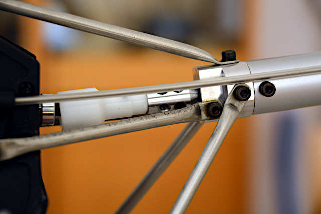
The hub connecting the tail rotor shafts turned out to be slipping. The shaft was removed to check the rear hub, which was still tight.
Maybe the main rotor had been stopped abruptly by ground contact and that shocked the front hub and let the set screws slip. The elastic shaft absorbed any further shock so the rear hub stayed unaffected.
Anyway, the set screws in the front hub just have been tightened again. Later, TMRF Rüdiger Feil sent me set screws with an edge, which somewhat cut into the shaft so they don't slip. All set screws were replaced then.
Both pinions show a proper contact pattern and no wear.
The main rotor shaft has several scratches, though. The freewheel's inner sleeve is bolted to the shaft's lower end but it's somewhat loose above. Maybe it has been all round pressed to the shaft by the main gear's radial push and tilted by the tail gear's axial push. In any case, something was wrong.
Both gears have no visible damage. The tail gear seems to have some wear but not bad at all. Not a single tooth is broken but it's possible that some teeth got struck when the main rotor hit the ground. Just to be safe, I wanted to have the gears replaced by new ones.
The freewheel in the center looks OK. There is just some grease leaked from inside but that is not unusual, as Rüdiger Feil told me.
There is more leaked grease on the bottom side but that could be expected because warm grease flows down.
Still there must have been something wrong with the freewheel. It had to be disassembled but I can't do that. Again I needed Rüdiger Feil's help and sent him the whole assembly.
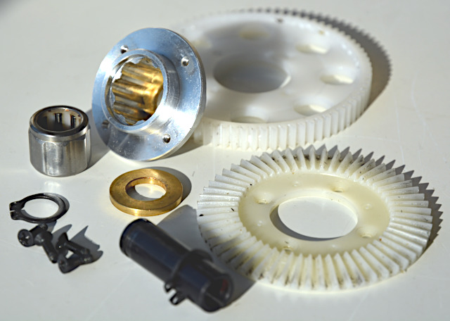
After disassembling and inspecting it, he sent the parts back – here they are. Most suspicious are the outer freewheel sleeve with notches inside and the middle part with asymmetric cams outside and rollers inside (both in the picture's upper left corner).
They both look shiny, leading to the suspicion that the cams slipped in the notches. At least that would explain why the grease got fluid (heat) and amperage increased (friction).
Anyway, something was wrong with the reversed freewheel and it could happen again if it would be simply replaced by a new reversed one. Rüdiger Feil promised he would come up with something else.
Replacements
Our mutual intention was to avoid falling back to a clockwise-turning main rotor.
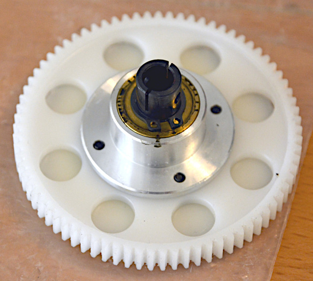
Seen from top, what he sent (this picture) – together with the old parts (previous picture) – looks like before, just brand new.
Main and tail gear will have to run-in a bit and will get some grease.
The bottom side looks different, though. Rüdiger Feil thought that it could have been wrong to reverse the freewheel's inner parts. In any case, it would be a better idea to reverse the whole thing so all parts are arranged like intended by the designer.
He still had to reverse the (black) inner sleeve because it has to be bolted to the main rotor shaft, but it has no notches or cams. And he had to make four spacer sleeves and use longer screws to have the gears in the correct position. Looks like a masterpiece now.
Of course it worked. The adjusting ring that holds the main rotor shaft vertically (not visible here) had a fraction of a millimeter play and was adjusted to be tight. Now the main gear touches the pinion exactly where it was before and that means also the tail rotor gear has the correct backlash again.
To know the main rotor's actual rotational speed at least from now on, I added a telemetry sensor. Two small magnets cling by themselves to the bottom of the freewheel's inner sleeve. With a piece of foam and two-sided adhesive tape, the magnetic sensor sticks on the helicopter's frame so it's less than 1 mm below the magnets.
The sensor's processor box is Velcroed to the frame. On the right side, the magnetic sensor is plugged in and on the left side the sensor bus leads go in and out.
The sensor's resolution is 100 rpm so it's less exact than the ESC's speed indication. Still both values coincide pretty well and I would get an alarm on the transmitter in case the freewheel would slip. I set the alarm level to 1400 rpm what is my minimum to fly the helicopter safely.
The tail rotor blades had nicks and dents since the crash landing. Still they were used for the test flight after the freewheel replacement but didn't show the desirable effect in crosswind then. That wasn't new but now there were even two reasons for a change.
So they were replaced by blades for the Neo550 which are a bit bigger and harder. Their surface is smooth (without relief HIROBO lettering) so red film could be applied where both leading and trailing edge are straight.
Tail rotor effect is now far better at any practical main rotor speed and the tail really "snaps in" after a yaw movement.
The helicopter is now even better than before – at least I feel so. Thanks to Rüdiger Feil (again German F3C champion in 2021, by the way) it is converted to counterclockwise main rotor in the first place and now in an even better way.
Telemetry
Because this model helicopter has a modern electric drive, it just has to be equipped with modern telemetry as well. At least it would be hard to ensure flight safety without telemetry:
The ESC is working as a governor here. The usual slider on the transmitter is now used to adjust the main rotor's set rotation speed instead of the motor's power. Rotor speed is held constant as long as the drive battery has a minimum voltage. (No matter what, the motor is powerful enough.) Just diminishing battery voltage, due to regular discharge during flight or for other reasons, won't cause any reduction of rotor speed and will thus go unnoticed.
In view of already short flight times of electrically powered model helicopters, their pilots take pains to get the most out of the drive battery. Power requirements can be quite different between flights. Squally wind or a jittery flying style need more power than usual because governor and flybarless system have to work hard then. Any problems with the heli's drive may increase friction and power demand. In any case, the battery will age rapidly since it is heavily loaded in a helicopter. At the end of its service life it will rapidly lose capacity, and as a result voltage badly drops even after a short flight time.
Taking such contingencies of battery drain and capacity into account would require a big safety margin in setting up the transmitter's throttle timer. Big uncertainty would mean an undue curtailment of flight duration so using the throttle timer would be unpractical. Gladly you'd allow yourself some telemetry, on top of the governor and the flybarless system. In any case, that's not really expensive today.
In this case, receiver and ESC provide even most of the desired values; just two extra sensors are used to monitor drive battery voltages as well as motor and battery temperatures, respectively. Something special is the FlightRecorder, which records the telemetry data so they can be analyzed later – possibly after an accident.
Most of the values are not just recorded and transmitted but also monitored for exceeding or falling below adjustable limits. Values and any "alarms" are shown on transmitter displays and announced by a voice-output device. To be useful, both ways of rendering need a sensible setup and therefore I devise a coherent plan in the form of a spreadsheet.
Sensor Setup
On the Multiplex Sensor Bus (MSB), every value to be transmitted is assigned a unique address, which is its line number in the transmitter display as well. My transmitter has an integrated display and an ancillary one. The former automatically branches to a three-line "page" in case an "alarm" is triggered by one of the values on this page. The latter always shows the same four-line page as long as I don't scroll to another one. That's why I try to make up four-line pages with values which I want to monitor simultaneously. Then, the three-line pages are composed, as good as possible, by properly sequencing the values in the four-line pages:
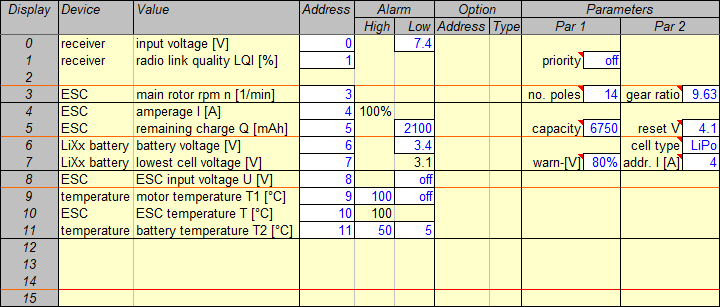
These are the basic telemetry device settings. Up to 16 values may be transmitted on the MSB; the display sequence (leftmost column) follows from the chosen bus addresses (fourth column). The four-line pages are marked off by black lines, the three-line pages by red lines. Alarm means optional upper and lower alarm thresholds while Parameters are mandatory and have to be set in the respective devices. (Options – that is maximum, minimum, or mean values – are not needed here because all telemetry data are logged.)
Only 10 of the possible 16 values are used here, an eleventh one just because there is still so much room. That's also why the two values delivered by the receiver have been left in their default places 0 and 1. For a 2s LiPo receiver battery, 7.4V under load is a safe warning (or alarm) threshold because it implies there is enough charge left for landing. "Priority off" means none of the values (or addresses) is transmitted more frequently than the others – that would be actually used just for a high-resolution variometer tone.
The main rotor's speed has been put in place 3, the last line of the first four-line page, so it appears in the first line of the second three-line page as well. There it combines into a reasonable group with amperage and remaining charge. Number of motor poles and gear ratio have to be specified because rotor rpm is derived from the motor's field frequency by calculation.
In turn, amperage and remaining charge combine into a reasonable four-line page together with battery voltage and lowest cell voltage. The ESC has a high-amperage warning threshold preset to 100% of its rating, which is 100A in this case. The 6s 7000mAh LiPo battery is charged to 4.17V (instead of 4.20V) per cell, which is why only 6750 is specified as capacity. 30% remaining charge, that is 2100mAh, is set as warning threshold. When the battery ages and wears out, less capacity has to be specified or a higher warning threshold. I prefer the latter but unfortunately both ways are equally inconvenient to set up with the MSB and my really old (2008) transmitter, respectively. The 4.1V reset voltage (slightly lower than 4.17V) is used by the ESC to recognize a fully-charged LiPo battery and its cell count.
Immediately after the drive battery has been plugged and armed, the special voltage sensor checks its cell voltages and reports its state of charge (in %) in the place of cell voltage. If one of the cells is below the voltage characteristic for "LiPo" cells charged "80%", a warning is issued – a safety feature. Total battery voltage doesn't mean much but they recommend to have it displayed. Then, if the 3.4V cell voltage threshold (set here) is underrun, the respective warning is displayed in the place of total voltage. Only the so-called absolute low-voltage alarm (threshold 3.1V preset for LiPo) is shown in the place of cell voltage. The 3.4V warning threshold is the default value and is tried and trusted by me – and it's not too high. It should be even raised when the battery ages and wears out, but the sensor doesn't allow that. If the sensor knows the amperage value's address ("4"), it can refrain from issuing a low-voltage warning in case of short amperage peaks.
Battery voltage and lowest cell voltage combine into a reasonable next three-line page with the following voltage as measured by the ESC – all three voltage values together. The last of them is the eleventh value mentioned above and is actually redundant because it will hardly differ from the first. Consequentially, its low-voltage warning is off. It's just a filler value here and on the next four-line page as well.
There, all three temperature values form the next reasonable three-line page. The motor is specified to withstand up to 150°C, but I set only 100°C as warning threshold because the sensor is not in the motor but simply clamped to its case. Coldness does no harm to the motor so its low-temperature warning threshold is off. The ESC has a predefined 100°C high-temperature warning threshold. The battery has the sensor just clamped to it like the motor, which is why I set 50°C and 5°C thresholds whereas internal battery temperatures should be kept between 60°C and 0°C. The lower threshold is on the off chance that the helicopter is outdoors in freezing temperatures and the battery cools off. Considering the existing safety buffers in the drive, it would be odd if a temperature alarm would really occur. The three values are interesting rather for later evaluation.
In this case, arranging all values in three-line and four-line pages worked out unusually well. That's not pointless even though I'll hardly look at a display while I'm flying the helicopter. But a clubmate could stand next to me and keep a close eye on both displays, and when the helicopter is adjusted on the ground I can even look myself. The reasonable and clear arrangement of values helps discerning the helicopter's "state of health".
Voice Output
My ROYALpro9 transmitter, bought in 2008, has no built-in voice output. For such cases, Multiplex brought out a special voice-output device, the Souffleur (Prompter in English). It has only five configuration memories, which are probably meant for different kinds of models. But I can get along with them even though I'm using them for individual model setups. So far the S-300 is my only helicopter with telemetry, anyway.
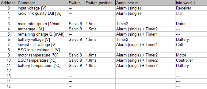
The voice-output setup follows from the basic settings. For every used bus address, type and frequency of announcements can be specified. The fifth column defines whether announcements are spoken in case of an alarm and/or periodically. In the third and fourth column, periodical announcements are made dependent on a transmitter switch setting. Info words are spoken prior to the respective value to make it distinguishable.
Amperage and remaining charge are obvious without info word because every announcement consists of a value and its unit. Main rotor speed is obvious for its unique unit as well, but I just want to have an info word here. The LQI's info word is preset and can't be removed, anyway (hence grey). All other values are voltages or temperatures and thus need an info word to tell them apart.
Info word, value, and unit – it takes some time to voice all that. Periodical announcements may easily clutter the voice output and that's why I want to hear most of them on demand only. With a transmitter switch (Servo 9) I can demand two groups of values: in center position (1.5ms), rotor speed, amperage, and battery voltage are called to be voiced every 30 seconds (Timer2); in top position (1.0ms) three temperatures every 30 seconds as well. None but remaining charge and cell voltage matter so much to me that they are always voiced, regardless of switch position, although just every 2 minutes (Timer1).
Almost all values are voiced if and when they exceed or fall below some threshold, in that case even with a preceded "Attention!". That may clutter the voice output as well and that's why I set all "alarms" to "single". The other option, "permanent", would mean an alarm is permanently (repeatedly) spoken and hence nothing else (or nothing at all) can be recognized. That did not prove feasible, to say the least, and I don't see a reasonable usage, either.
So in case a temperature threshold is exceeded, the respective alarm is output only once. But that ought to alert me, and if I want to monitor the temperature further on I can flip said switch to its top position. That will call the three temperatures immediately and once again every 30 seconds. Alternatively, I can flip the switch up and instantly back down to call the values only once, and I can repeat that at random intervals. It would be hard not to voice even three temperatures in one chunk; after all several switches for voice output would be too complicated just in a distressing situation. But the three temperatures are interrelated, anyway, and if one of them is too high the other two may be worth knowing as well.
Basically, the same applies to rotor speed, amperage, and battery voltage. But for the former and the latter, no alarms are provided by the respective sensors. Perhaps rotor speed is seen as a mere effect of the two other factors, and with the ESC working as a governor it is maintained constant, anyway. However, instead of total battery voltage, the lowest cell voltage is monitored, which is more important and whose limit values are more easily remembered than those of a number of cells.
Receiver voltage and LQI are voiced as an alarm but not periodically, so only if problems arise. These are made as unlikely as possible by maintaining the battery and by properly orienting the antennas, respectively. By means of large capacity and short distance to the transmitter, respectively, both have quite a safety buffer.
The voltages measured by the ESC and by the special sensor on the battery should be equal. Just because there was a convenient place, both values have been included in the display. The former voltage is not voiced, though, because it's redundant and therefore becomes subject to the necessary axing of announcements.
After all it should be clear now that voice output significantly contributes to flight safety. While flying a helicopter, we hardly have time to look on a display – not only but especially in case an alarm is just signalized by sounding a beep. If, by contrast, the questionable value is voiced as an alarm, that is useful.
Flight Analysis
The FlightRecorder records all telemetry data (ten times a second) to have them analyzed later on a computer and this way see them in context and over the whole time of a flight. Especially after accidents it would be helpful to see the drive data also related to the heli's movements and the control inputs. The latter can't be recorded, though.
A sensor with a Prandtl tube could provide at least altitude, its change (variometer), and airspeed. In a model helicopter, though, which is flown at low altitude and at slow speed, it would be not really useful because its precision or resolution, respectively, is not up to the task. It just wouldn't be worth it.
At a first glance, a GPS could provide all movement data, and it would be even possible to plot the whole flight path three-dimensionally and including speeds. However, considering the performance of the GPS in my Senior Telemaster Plus (see here), it seems that a GPS is precise as long as it's in motion but produces erratic values when standing still. Hence, a model helicopter which spends a lot of time in hover flight seems to be not exactly a typical use case.
So basically, only drive data are recorded during flights. (A distinctive counter-example is the mentioned airplane – my Senior Telemaster Plus.) Nevertheless, a GPS is in this helicopter, just because it's possible and simply to see how good or bad it works. In this case it's the newer version 2 with better antenna and it's set to "slow aircraft" in order to possibly avoid the erratic values which occurred in the other case. (That means horizontal speeds up to 79 km/h and vertical speeds up to 54 km/h, and this helicopter should stay in that range.)
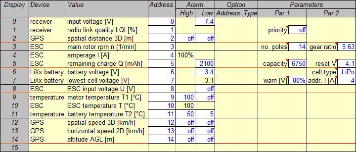
The GPS 3D location data are logged by the FlightRecorder in any case. They are used to render a flight path in Google Earth. In diagrams, speed and altitude and perhaps also distance are useful data to plot over time. These have to be displayed (sent on the MSB) during flight so that the FlightRecorder can log them.
While flying a helicopter, such values should be hardly of any interest. Distance may be an exception, which is why it has been put into the former gap (place 2). Here it's indeed a meanigful complement on the first three-line as well as four-line page. "3D" means spatial distance, that is in the line of sight and not on the ground and seems to be more reasonable in case of a helicopter.
Speed and altitude have been just appended to the other values (places 12 to 14) but yet constitute a meaningful three-line as well as four-line page. Again, "3D" means spatial or in the line of sight while "2D" means on the ground. The former speed includes vertical speed (variometer), which is not separately displayed by the GPS. Both speeds are relative to the ground, that is not to the air, and a comparison gives at least a clue of vertical speed.
No warning thresholds have been set for the GPS values. Warnings are not needed during flight because this helicopter is flown only slowly and at close range (as well as low altitude). So because warnings are pointless they would be even annoying. GPS values are just logged for future reference.
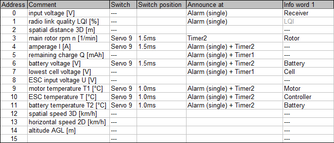
Since no warnings are needed for GPS values and no announcements by voice, either, there are no changes or additions to the voice output setup.
Just a correction had to be made: Any low cell-voltage warning at address 6 (yes: 6 – see above) should be voiced.
Example
By way of illustration follow the telemetry data logged during the flight shown in the video presented above. First, this is the flight path as a synopsis of the flight:
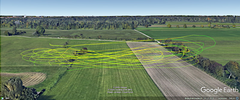
In the course of the flight, 14 more or less horizontal loops have been flown, some as figure eight, others as approaches with following spot turns or even with intermediate landings. As the pilot, I stood in the runway bulge on the left, the video man a bit to my right. This way, we avoided to have the sun in the corners of our eyes and the helicopter was well-lighted. The turns on the right side (in the east) have been flown a bit higher to keep visual-line separation from the trees. Some turns actually went past the line of trees.
This depiction of the GPS 3D location data gives the impression that some turns went even through the trees, and take-offs and landings seem to have been underground. The ways between runway and setup bench are not shown at all. That's all because the altitude specified by the GPS is more or less inaccurate, that is too low. Probably, the GPS device is too simple (cheap), but the flight path over ground is still displayed very accurately.
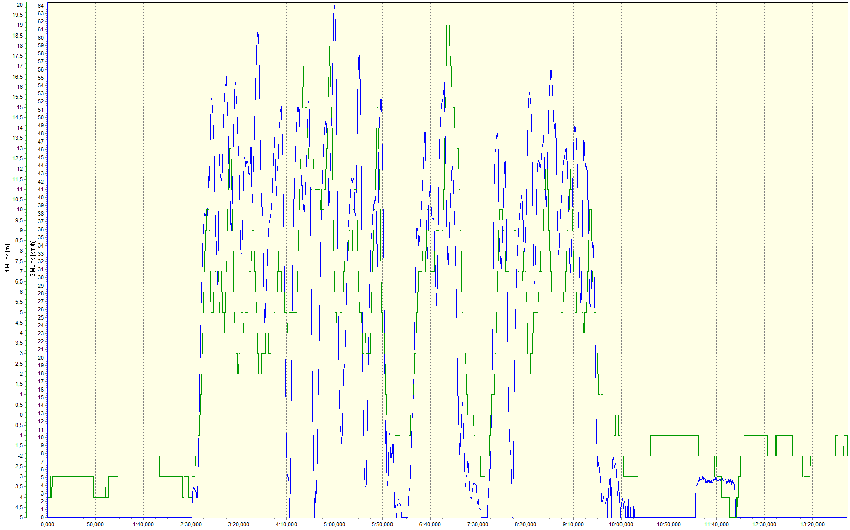
That's how the data are shown in diagrams. For the first 2½ minutes (0 to 2:30) after the flight battery had been armed, the helicopter stood on the runway. Telemetry was checked and then the rotor run up, what took 40 seconds. During this time, indicated altitude fluctuated between -2 m and -4 m, for whatever reason. The two intermediate landings (6:10 and 7:35) puportedly went down to -2 m or -3 m, respectively, and the final landing (10:10) to -3 m as well. Then, while the helicopter was still on the ground, indicated altitude went up to -1 m, but while the helicopter was carried to the setup bench (11:15 to 12:00) it went down to even -5 m. Until telemetry was switched off, altitude fluctuated up to -1 m and down to -3 m – the helicopter still on the setup bench. Compared to 20 m maximum altitude during the flight, -5 m maximum error is quite a lot, even if the course of altitude is basically correct during the flight, as shown by the previous picture.
Indicated speed might be flawed as well but no errors show up; the blue line looks reasonable. It shows more or less vigorous acceleration after take-off (2:30, 6:15, 7:10), careful approach for landing (6:00, 7:30, 10:00), and three spot turns (4:15, 4:40, 8:05) that turned out well (pun not intended but left). Peak speeds (up to 64 km/h) don't correspond to peak altitudes because speed is reduced in the turns flown over the trees. While the helicopter is still on the ground or on the setup bench, indicated speed is correctly 0 km/h; while I'm carrying it to the setup bench (11:15 to 12:00), indicated speed is 4,5 km/h – could be correct as well.
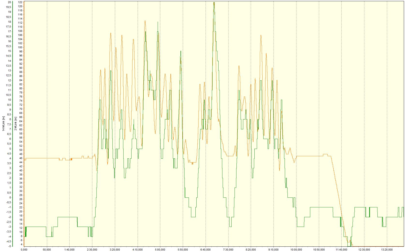
This is a comparison of altitude and distance. Also this orange line looks reasonable. While the helicopter is still on the ground or on the setup bench, distance has only small "jerks" by 1 m, that is the increment or resolution of this value. It begins at 46 m before the flight (0 to 2:30) and ends at 47 m after the flight (10:0 to 11:15) because that is the distance between the take-off or landing position, respectively, and the place where telemetry had been switched on – the setup bench. Then, it goes down to 3 m because the helicopter had been carried back to the bench but put down at the bench's other end (11:15 to 12:00). Finally, distance stays constant – other than altitude.
The pulled-up turns are recognizable by peaks of altitude and distance at the same time. The biggest turn includes the farthest and coincidentally highest point of the whole flight. The landings (6:00, 7:30, 10:00) – at places close together – are recognizable by "troughs" in both lines; spot turns (4:15, 4:40, 8:05) are not apparent, though.
Despite the limitations (inaccurate altitude, abstract illustration) the GPS values help analyzing the flight. The device used here (version 2 with better antenna) and its setup for "slow aircraft" make for reasonable values without erratic fluctuations. Hence a GPS can be useful also in a helicopter. Now to the actually important telemetry data:
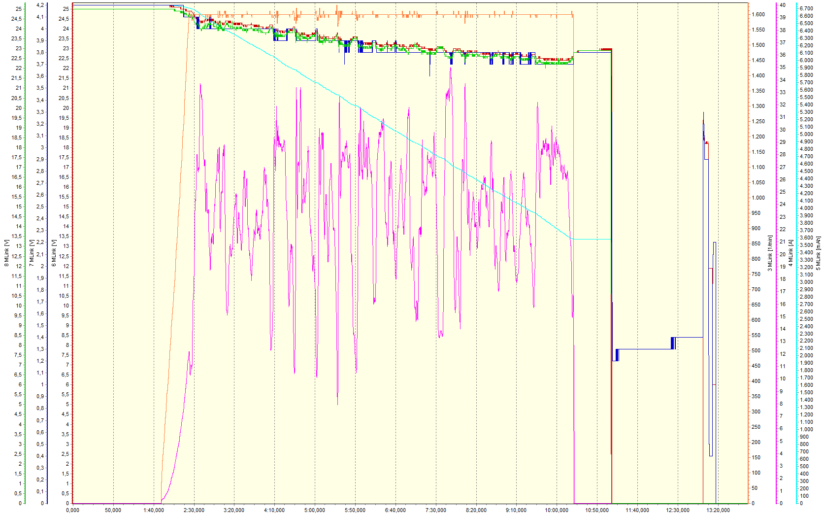
Three voltages are measured on the 6S LiPo flight battery, or actually 2x3S LiPo flight batteries and all of them with 0.1 V resolution. A separate sensor plugged to the batteries' balancer connectors takes total voltage (red) and actual lowest cell-voltage (blue). The latter's steps are six times as big as those of the former, but both lines are overlaid by adequate scaling and basically coincide. There is at least one short drop of cell voltage, but it doesn't go below the warning level. Even if it would, that wouldn't probably trigger an alarm because the sensor suppresses such alarms during short amperage bursts.
The ESC measures total voltage (green) as well as the sensor on the batteries does (red), but it displays values lower by an average of about 0.2 V due to the resistances of the XT90 connectors, the AntiFlash device with master switch, and the cables in between. (At 23 A amperage – see next paragraph – the resistance is about 8 mΩ.) Except for this amperage-dependent offset, the green line coincides with the red line. That said, there are small spikes down in the green line which are proportional to amperage peaks as well as the resistance between battery and ESC, and bulges in the red line which are proportional to the battery's own resistance (about 20 mΩ). Apart from these small and short-waved fluctuations, the voltage lines are smooth and show a LiPo battery's typical discharge process.
Comparing the voltage lines and the amperage line (pink) shows the reason why: Amperage fluctuates heavily but around a quite constant average, which is somewhat higher only during the hover (9:35 to 10:20) prior to the final landing. The discharge line (light blue) – effectively amperage added up – makes it obvious: It's virtually straight and drops a bit eventually. Taking the end-points, mean amperage is easily calculated: 23.3 A from 3:20 to 9:35 and 28.0 A from 9:35 to 10:20, but the latter is inaccurate because the line's last part is short. Anyway, that's only 3.3C or 4C load, respectively, on the 30C battery.
The light-blue line's long first part isn't quite accurate, either, because figure-eights make for smaller amperage fluctuations – both up and down – than approaches with following spot turns. During an approach, the helicopter is pitched up and slowed down with small collective pitch, but then kept in hover with a lot of collective pitch. During a figure eight, somewhat more collective pitch is needed in turns and less in fast forward flight. In the final hover (9:35 to 10:20), amperage fluctuates much less, perhaps because only small collective pitch corrections are needed to keep the helicopter at a certain altitude. Shortly before touch-down (10:05 to 10:20), amperage seems to be lower by 2 A, probably due to ground effect.
While running up the main rotor (1:50 to 2:25), the amperage line (pink) is parabolic and then settles at 11 A. Rotor speed (orange) increases virtually linearly up to 1600 rpm, whereupon it is well stabilized. Just the big amperage fluctuations during approaches with following spot turns let rotor speed go up or down by up to 30 rpm (1.9%) or 40 rpm (2.5%), respectively, before the ESC/governor is able to react. Rotor speed plummets at the end of the flight (10:20) simply because the ESC/governor is switched off. When the flight battery is disarmed shortly after (11:10), the other lines plummet to zero as well or become absurd.

Finally, the temperatures of motor (dark yellow), ESC (magenta), and battery (light blue) are compared with amperage (pink), which is their common cause.
Battery temperature (light blue) rises by only 6°C/11°F during the actual flight, and by 0.5°C/1°F before and after. At least the small increase after the flight may be accountable to the heat developed inside the battery. It flows only slowly outwards to where the sensor is. It's striking – and mysterious – that the temperature rise is shortly interrupted sometime during the flight, in fact during all flights. Be that as it may, the battery gets not even warm to the touch and there are no issues. The steep decrease in the end (13:30) just means that the battery has been taken from its support and the sensor is exposed.
No problems with the motor (dark yellow), either, even though it gets considerably hotter. During the flight, more and more heat seems to accumulate, despite the built-in cooling fan. The figure-eights flown close to the end of the flight (8:00 to 9:30) need so little amperage that temperature even slightly drops (below 52°C/126°F). It rises again during the final hover, but it's a mystery why it rises even more (to 55°C/131°F) just in ground effect (10:05 to 10:20). The rise to 62°C/144°F after the ESC has been switched off (10:20) is due to residual heat in the motor; the abrupt drop to 58°C/136°F (11:40) is mysterious.
Initially, heat seems to accumulate in the ESC/governor (magenta) as well. Anyway, its temperature rises up to 82°C/180°F (7:50) but then drops to 73°C/163°F during some figure-eights (9:30). During the final hover, it rises steeply and stops only at 82°C/180°F just because the flight ends (10:20). It would have risen even higher, although not quite to the 100°C/212°F warning level. Even without airstream, cooling is sufficient since the ESC has been fastened on edge under the helicopter's bottom to let cooling air to both sides. After the ESC has been switched off (10:20), temperature drops quickly and plummets to zero when the flight battery is disarmed (11:10).
Change
After the 2020 flying season I purchased a new transmitter. That was triggered by the acquisition of another, even larger helicopter – the ROBAN Bell 429. The new transmitter is actually "a size smaller" than my old one but it has 12 channels (instead of 9), is new, and is more modern. It has integrated voice output, an operating system similar to that of a smartphone, and a touch screen. In the telemetry display pages, the font size and hence the number of displayed values is adjustable. Here are both transmitters side by side:
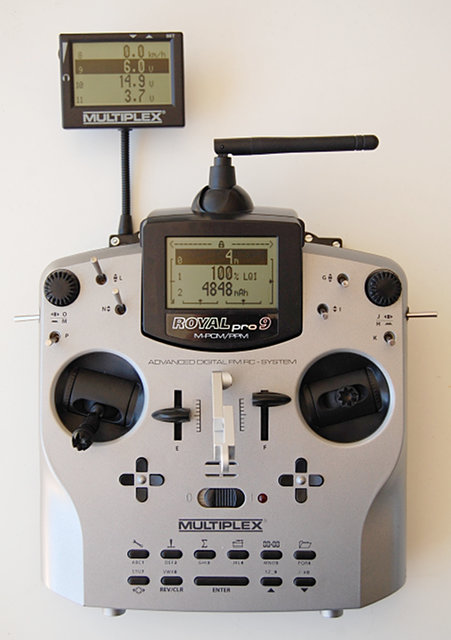
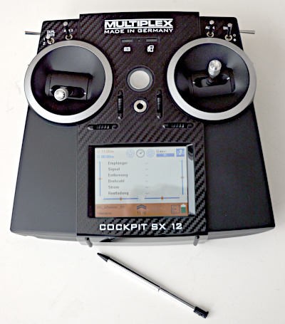
Obviously, the old transmitter (bought in 2008) shows the telemetry values much clearer than the new one (bought in 2020), but that's just the way things are. When flying the helicopter I don't look at the display, anyway, but rather rely on voice output. While the helicopter is on the ground, there is no problem reading the values, for instance to check main rotor speed or a temperature.
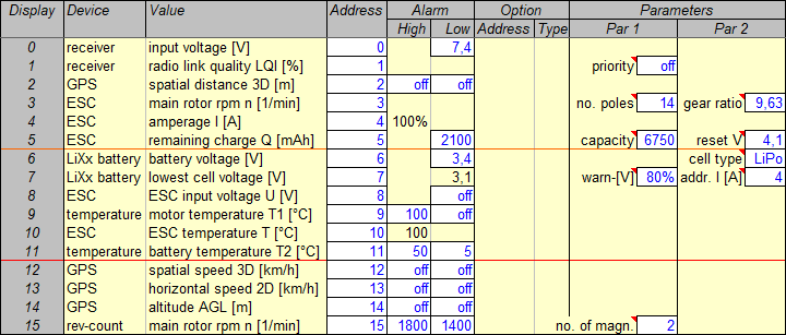
For me, six lines (values) per page is the best compromise between overview and readability. The display has been adjusted to that by dragging the touch pen. In this plan, two pages with six lines each are marked off so a third page with four lines remains.
Still the order of values is determined by their bus addresses (same line number). Still one can scroll the pages, now just by swiping on the touch screen.
Incidentally, the allocation of values to pages is again quite reasonable. The first page combines all values which might be interesting during flight, even if the pilot can't look at them (but maybe a clubmate). The second page combines all voltages and temperatures which are displayed in case of an alarm. Again, the pilot can't read them but there is voice output instead. On the third page remain the GPS values which are meant for logging only. All in all, the telemetry display is good but not really important.
That's why the order of values wasn't changed when a new sensor was added – a rotational speed sensor. It's meant to detect if and when the autorotation clutch is again slipping (see above). It does not substitute but rather complement the ESC's rotational speed display so I can compare both values (and because it has only 100 rpm resolution). A good option would be displacing the GPS's "spatial distance 3D" from line 2 to the last line and putting the new rotational speed value previous to the old one. However, the GPS had to be put off the bus, the new address set on a PC, and the GPS plugged into the bus again. That was too tedious for me or isn't worth it, respectively, because the telemetry display is not really important. The additional rotational speed display is now simply in the last line which had been free so far.
On the transmitter, between the stick units and above the round main switch, are a battery symbol and a gas pump symbol. The respective LEDs above them are lighted as an additional warning in case the receiver battery voltage is too low or the drive battery is discharged, respectively (according to the alarm levels set in the sensors). To this end, these two telemetry values need to have assigned certain bus addresses defined by the transmitter manufacturer. Here, receiver voltage has the correct address 0 but remaining charge ought to have address 4. The two LEDs are well-meant but actually redundant due to voice output. Even if only the ESC would have to be reconfigured – it's not worth it for me to take it off the sensor bus, set two new addresses on a PC, and re-plug the bus again.
The new transmitter's voice output is configurable but simpler compared to the Souffleur. With a bit effort, it's possible to generate special sensor value announcements and load them into the transmitter. However, these announcements are bound to fixed addresses then. So for all models the same respective addresses (for instance for rotor speed) would have to be used. That's virtually impossible so the standard announcements (for instance “sensor 3”) are even more meaningful. They are useless, though, which is why I replaced all of them by a short beep to shorten announcement time. It's still possible to distinguish all values by their units, or in case of several voltages or temperatures by their values. And short announcements are good in any case.
Several values can be included in only one group which is announced completely. But not only a switch can trigger the annoncement but also tilting or moving the transmitter. That's how I trigger the announcement of a few critical values: remaining charge, lowest cell voltage, ESC temperature, and (true) rotor speed (by the new sensor). Separately, remaining flight time is announced by tilting the transmitter.
By the way, voice output is also assigned to switch positions. That's very convenient for me since I keep forgetting which switch and position is assigned to which function. Now I can simply try and I'm prompted. Of course, I do that only before the helicopter is activated; then I can again keep it in mind for the next few flights.
Enhancement
Only after some pondering it dawned on me that the ESC input voltage might be useful as another warning level, in addition to the cell voltage warning and not just redundant. Now the warning level in the ESC had to be set up differently and the ESC had to be disconnected from the telemetry sensor bus and plugged to a computer. While I was at it, it was easy to change more parameters in the ESC and to disconnect and set up the rotational speed sensor, the voltage sensor, and the GPS as well. That was an opportunity to reshuffle some of the telemetry values for a better, that is neat arrangement.
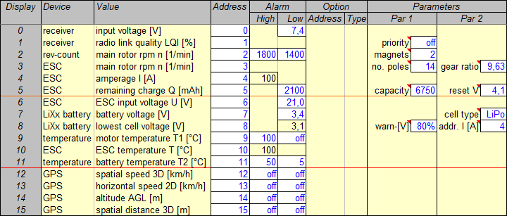
The two main rotor speed displays are in consecutive places now.
Lower and lower voltage warning levels are in consecutive places now. (21.0 V battery voltage is equivalent to 3.5 V cell voltage.)
All GPS values are combined in the last four-line page.
This whole reshuffle was just triggered by changing the ESC input voltage warning level. That in turn was done to follow the safety plan that I had devised for my new ROBAN Bell 429. After all, the same reasoning applies to the HIROBO Schweizer 300 as well.
Yet it's only a safety add-on in this case because a big battery (7000 mAh) is used here. The throttle timer is set to 11 minutes, giving 10 minutes net flight time after which idle cell voltage is still more than 3.8 V – remaining charge more than 40%. Any telemetry alarm could be expected only from a too cold battery or a bad cell.
Drive
To render the model's performance in the REFLEX XTR² flight simulator, the drive characteristics had to be ascertained. "Drive" means electric motor, main and tail rotor gears and shafts, and both rotor heads. Some parameters were specified by the motor and model manufacturers, respectively, some had to be measured, and the rest was calculated. Finally, after the helicopter had been flown for the first time, telemetry data recorded in-flight allowed for tweaking the calculations to give even more realistic (or accurate) values. The final calculation spreadsheets are available for download.
Parameters
The motor's manufacturer specified 930 rpm/V specific rotational speed (kv) and 11 mΩ (milliOhm) internal resistance (impedance, Ri). The third characteristic required to calculate the motor's performance, idle (no-load) amperage (current, I0), had to be measured. To this end, the motor was just clamped to the workbench and run with the designated ESC/governor and a 4s LiPo battery. The ESC's telemetry showed both rotational speed and amperage. I0 turned out to be 2.7 A at 15000 rpm (equivalent to 1560 rpm main rotor speed).
Similarly, amperage was measured after the whole "drive" had been assembled (see above). That is, motor and gear were mounted in the main frame, main rotor head and swashplate were linked to each other and the servos, and tail rotor gear and head were working. The ESC/governor was set to 1560 rpm main rotor speed and after a noticeable run-in of the whole drive the no-load (no blades) amperage I0 turned out to be 3.4 A now. So main and tail rotor "gear" made for an additional 0.7 A amperage draw. A simple calculation resulted in more than 96% "gear" efficiency (which, as the percentage of torque transmission, by definition includes any additional friction losses under load).
That, together with the specified gear ratios, was enough to render the drive in the flight simulator. I didn't even check the specified values (except the gear ratios) because that would be hard and because the calculations are simplifications, anyway. Later, these were even tweaked but the data used for that had been measured by telemetry and are not really accurate, either. Yet the performance calculations are quite useful, showing the electric drive's overall efficiency, load factor, and power reserve in reasonable accuracy. Anyway, the calculations have not only been tweaked but also adapted to hovering at different main rotor speeds.
Hovering at 1520 rpm
The calculations consist of two cases: full power and partial power. Primarily the latter is interesting for helicopters, which have some sort of governor to maintain a constant rotor speed. HIROBO recommends 1500 to 1600 rpm and we set 1520 rpm for the first hover test. The recorded telemetry data showed 29.5 A mean amperage with considerable fluctuations to control rotor speed and the helicopter's altitude (as well as attitude). Anyway, the calculations were adapted to 1520 rpm at full and partial power and 29.5 A at partial power. The former case results in maximum amperage (98.0 A) and the latter in a "throttle ratio". That's the percentage of full voltage which is equivalent to what the ESC really does to maintain the preset amperage and speed and which is determined by simply trying: 80% for 29.5 A and 1520 rpm.
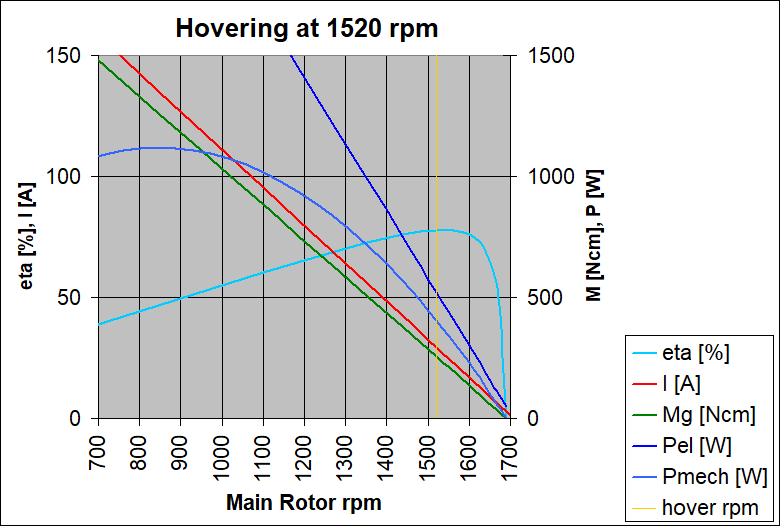
So this is a diagram for 80% power setting, which is needed for hovering at 1520 rpm and automatically done by the ESC/governor.
Advancing to 100% at still 1520 rpm, to make for a massive climb with maximum blade pitch, could draw up to 98.0 A, but this massive power reserve (3.3 times average) is not shown here.
It's a theoretical value, anyway, since it's certainly not needed in practice and since it's even 30 A more than the motor can stand continuously (while the ESC could even stand 100 A).
Amperage I (red) and moment (torque) M (green), which is a result of amperage, are both inversely proportional to rotor speed. Their lines' slope is quite steep so this is a fairly "rigid" drive – due to its high quality, that is low electric, magnetic, and mechanical "friction". That means a random reduction of speed would make for quite some increase of amperage and torque what in turn would boost speed back to average (and vice versa). The governor is really needed (or at least used) to "advance throttle" in case of pitch changes, both collective and cyclic.
Since voltage ("throttle") is held constant and amperage is inversely proportional to rotor speed, electric power Pel (dark blue) is inversely proportional to rotor speed as well. All values below about 1300 rpm are not really important because the motor's maximum continuous amperage is exceeded there. Still it's interesting to see that mechanical power Pmech (blue) has a maximum at far lower speed – always at half maximum speed, which is 850 rpm at this throttle setting. This value is not important for a helicopter with governor, which after all advances throttle to increase power. It just shows that the drive is operated at fairly high motor speed and (thus) low power.
This is where the drive is most efficient while efficiency would be awful at maximum mechanical power. Indeed this drive is operated where its efficiency curve eta (light blue) is at its maximum, and it's a spectacular 78% efficiency overall (taking all electric resistances and all mechanical friction into account). So the motor is an excellent choice for this helicopter, both for its fitting kv value and high efficiency. It makes for minimum amperage draw and maximum flight time at the chosen settings. For even longer flight times, even lower rotor speeds have to be chosen.
Hovering at 1420 rpm
That's why a 100 rpm lower, 1420 rpm rotor speed, which is not recommended by HIROBO, has been tested for hover as well. The helicopter was still perfectly controllable (so testing even lower speeds seems promising) and mean amperage was 2.0 A lower: 27.5 A. That must be an effect of the rotor blades being operated at medium angles-of-attack (AoA). A bit more AoA to compensate for lower speed (rpm) increases the lift coefficient substantially but the drag coefficient only slightly, so drag decreases with speed (rpm). (It would be the other way around close to stall-AoA.) The full-power case results in 113.7 A maximum amperage and the partial-power case in 74% power setting required for 27.5 A at 1420 rpm.
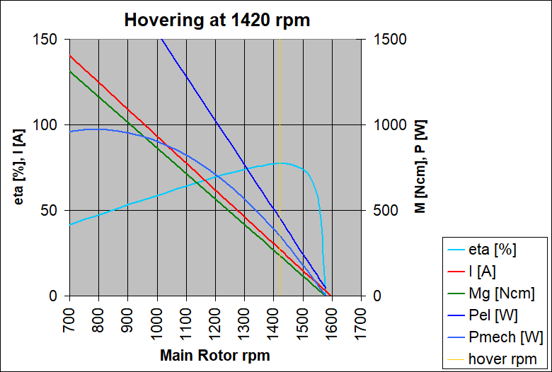
This diagram for 74% power setting, which is required for the lower 1420 rpm rotor speed, shows lower amperage, torque, and power as well.
Maximum amperage (113.7 A) is higher, though, because full (100%) power at lower speed just means more amperage and torque, and now it's more than the ESC/governor can stand continuously.
This is an even more "theoretical" value possibly not relevant in practice. While the main rotor's torque increases substantially (yet still not boundlessly) when its blades stall, just this blade stall should be prevented by limiting the blades' pitch.
Remarkably enough, the efficiency curve eta (light blue) is shifted with all other curves in the diagram. So the drive is still operated at peak efficiency, independent of rotor speed or power setting, respectively. The motor's kv value just fits the helicopter, and its power is plentyful even given the helicopter's weight. At lower power settings, the motor is less working to its capacity what slightly reduces its efficiency. But 77% overall (1% less) is still a spectacularly good value.
Hovering at 1100 rpm
Finally just a theoretical experiment:
<Begin-of-theoretical-experiment> I was pondering over feasibility
and usefulness of longer main rotor blades
(see above).
The helicopter's simulator model – which has the correct drive parameters
thanks to the calculations discussed here – was used to test longer blades
for rotor speed and blade angles. It turned out that the hover blade-angles
recommended by HIROBO for the standard blades (477x39 mm) at 1500 to 1600 rpm
require only 1100 rpm rotor speed with longer and wider blades (580x43 mm).
Now the calculation's full-power case results in even 163.9 A maximum amperage
and the partial-power case in only 58% power setting required for 21.5 A at
1100 rpm. This amperage value is just an educated guess but it should be in
the ballpark.
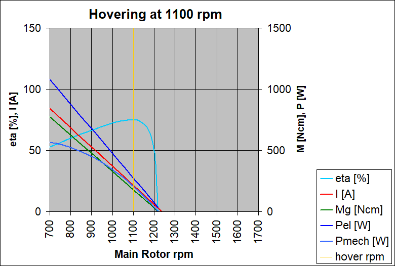
Corresponding to the the low 58% power setting required for the really low 1100 rpm rotor speed, all parameters are much lower now.
"Theoretical" maximum (full-power) amperage (163.9 A) is even higher now due to even lower rotor speed. Still that shouldn't be a problem in practice as long as blade stall is safely prevented by limiting the blades' pitch.
There should be no other problem for the motor, either, since mean amperage is even lower now. The motor is just even less working to its capacity and its efficiency reduced further. 75% overall efficiency (another 2% less) is still not bad at all. However, the motor is so underloaded that I would rather consider a smaller version from the same Pyro line. There's only the MINIPYRO 400-10, having the still fitting kv 1000 (instead of 930) and enough power. Efficiency might be higher by 2% again. But as stated above, I wouldn't use such long blades, anyway, for their notable drawbacks. They just don't really fit this helicopter. </End-of-theoretical-experiment>